A Study on Burst Pressure of Carbon Steel Pipe with Different Wall Thinning
Abstract
The pipes of energy plants and ocean structures are subject to local wall thinning, resulting from severe erosion-corrosion damage. Therefore, evaluation of failure pressure and fracture behavior of pipes must be necessary for getting integrity of them. This study investigated the failure behavior of carbon steel pipes with varying degrees of localized wall thinning under internal pressure conditions. The parameters included wall thinning shape, length, and depth. Failure mode was influenced by internal pressure, wall thinning length, and depth. A thickness ratio of 0.2 or more could safely withstand the internal pressure. Acoustic emission (AE) signals were detected when plastic deformation began. The dominant frequencies were found in the ranges of 78~195 kHz and 292~351 kHz.
Keywords:
Carbon Steel Pipe, Wall Thinning, Finite Element Analysis, Burst Behavior, Acoustic Emission1. Introduction
High-energy carbon steel pipes are used extensively in pipeing systems of power plants. Since erosion/corrosion from high temperature and high-pressure conditions can cause significant wall thinning, increasing the risk of pipe rupture. To evaluate for piping degradation mechanism of a nuclear power plant, Ferng et al. is developed the model to predict the amount of local wall thinning around the surface of fitting.1) Lee et al. found a significant decrease in pipe wall thinning due to flow accelerated corrosion and erosion-corrosion in nuclear power plants.2) Khan et al. was compared experimental and numerical analysis the causes of failure of 90° and 45° elbows made from API 5L X65 steel. They were proposed remedial actions for preventing the erosion-corrosion of 90° and 45° elbows.3) Hasegawa et al. were evaluated the wall thinning in pipes by comparing with the field rupture data and pipe burst test data.4) Kang et al.5) investigated the precipitation behavior at high temperatures and the influence of precipitates on high-temperature deformation using Incoloy 825, which has excellent corrosion resistance, high-temperature, and low-temperature properties and is used in various industries such as chemicals, petrochemicals, and nuclear power. The development of a defect on pressurized pipeline could easily threaten its structural integrity and if not managed on time could lead to burst failure. Tee et al.6) were carried out to calculate both (gouge and pit corrosion) cases of defect damage on pipe structure considering their different geometries. Corrosion had more deteriorating effect on the pipe burst strength compared to gouge. Kim et al.7) proposed the local allowable wall thickness (LAWT) evaluation method for local wall thinned pipe subjected by internal pressure and bending moment. Also, LAWT was evaluated for simplified thinned pipe and the effect of axial extent of thinned area on LAWT was investigated. Oh et al.8) evaluated plastic limit loads of pipes with local wall thinning under combined pressure and bending, by quantifying effects of the axial extent and the shape of local wall thinning. The effect of the axial extent on plastic limit loads is not so significant for bending but could be more significant for internal pressure. It is found that the effect of the shape of local wall thinning on limit loads could be significant. Takahashi et al.9) were tetsted using elbow specimens with local wall thinning by low-cycle fatigue tests. Finite element method was used to calculate loss from erosion-corrosion. The fatigue lives estimated by the calculations were close to those obtained by the experiments. Fahed et al.10) were evaluated the burst pressure of pipelines with internal corrosion defects of carbon steel API X42, X52, and X70 pipe grades. They were investigated the influence of the corrosion defect parameters (depth, width, and length) to the overall burst pressure of the pipe. Based on the results from the parametric study, the analytical closed-form expression to predict the burst pressure of internally corroded pipes derived, which was agree well with the experimental results.
However, a monitoring for failure in wall-thinned pipes is essential for effective prevention strategies of pipe system. Acoustic emission (AE) are useful to evaluate for failure of wall-thinned pipe under internal pressure. Nam et al.11) investigated failure modes of locally wall thinned pipes (all-circumferentially thinned pipe and partially thinned pipe) and carried out counts, accumulative counts and time-frequency analysis of AE during the bending test. Barat et al.12) carried out for analytical modeling of AE signals in thin-walled objects. This model allowed one to obtain model signals that have the same spectrum and waveform as real signals. The attenuation parameters of the AE waves for various characteristics of thin-walled objects were obtained, and understood the probability of defect detection at various distances between the AE source and sensor.
This study asummed the wall-thinned that occurs over time in pipe using SPPH380 high-pressure carbon steel pipe. The thinned-wall depth and length was artificially introduced mechanical machining. The thinned-wall pipe was then subjected to internal pressure to evaluate the failure behavior according to the thinned-wall geometry. The applied internal pressure was set to match the operating and design pressures of secondary coolant pipes in a nuclear power plant. Strain gauges were attached to the center of the thinned-wall portion to measure the strain in the pipe under internal pressure. The failure behavior and strain data obtained from the experiment were compared with the results of finite element method using ANSYS. Additionally, the dominant frequency of AE was measured and compared with the failure behavior.
2. Experimental method
The experiments utilized carbon steel straight pipes designated as "SPPH380" for high-pressure service. SPPH380 is used in piping systems with high operating pressure of approximately 350℃ or less. These pipes had an outer diameter (2R) of 48.6 mm and a thickness (T) of 5.1 mm. While erosion-corrosion typically causes wall thinning on the inner pipe surface, this study artificially induced flaws on the outer surface due to the challenges associated with creating inner surface defects. Previous research indicates that failure modes for pipes with inner and outer flaws exhibit similar characteristics.5)
Fig. 1 illustrates the various flaw geometries employed in the specimens: (a) circumferential, (b) single-plane, (c) double-plane, and (d) arc-shaped flaws. Flaw depth (d) and length (L) were controlled variables. The thinned wall thickness(t) was measured using an ultrasonic thickness gauge. Detailed pipe dimensions are presented in Table 1.
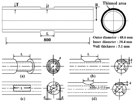
Pipe specimen geometries with wall thinning. (a) Circumferential flaw, (b) Single plane flaw, (c) Double plane flaw, (d) Arc flaw
The Circumferential flaw (a) was machined along its circumference. The single plane flaw (b) had a thinned plane whose shape was rectangular. The double plane flaw (c) had also thinned planes whose shape was rectangular and symmetrical. The arc flaw (d) had a thinned plane whose shape was arched.
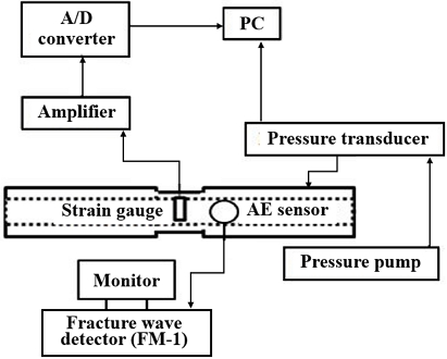
The operating and design pressures were set at 6.2 MPa and 15 MPa, respectively. Fig. 2 illustrates the experimental setup for internal pressure tests. After creating thread grooves, both pipe ends were sealed with stoppers. Oil was injected using a hand pump to apply internal pressure until it reached the design pressure of 15 MPa. A strain gauge positioned at the flaw center recorded strain and pressure data at a rate of 10 times per second.
Real-time acoustic emission (AE) signals were monitored using a Fracture Wave Detector (Model FM-1, Digital Wave Corp., Englewood, CO) equipped with a 1 MHz wideband sensor. Detected AE signals were digitized using an AD converter and subsequently analyzed using time-frequency analysis.
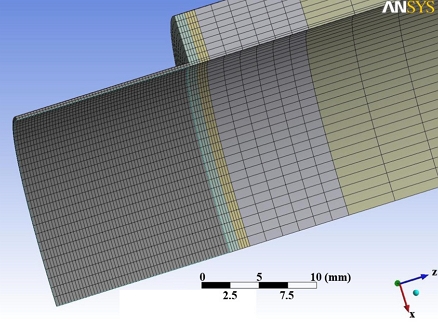
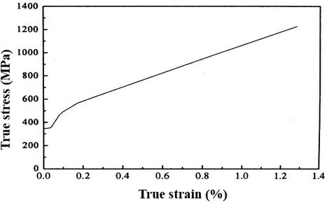
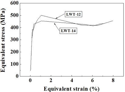
The failure behavior of the pipe was calculated using the three-dimensional elastic-plastic finite element method (FEM) using ANSYS, Version 11.0. The mesh modeling used Solid 186 as a hexahedral 20-node element and was divided into eight symmetric segments, with only one-eighth modeled for analysis (Fig. 3). Material properties for SPPH380 were assumed isotropic hardeding law, with a Young's modulus of 206 GPa and a Poisson's ratio of 0.3. The design pressure was applied to the inner surface of the pipe as in the experiment.The true stress-true strain curve used in the FEM is presented in Fig. 4.
3. Results and discussion
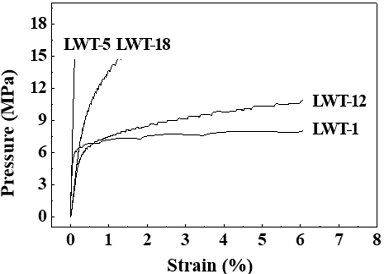
Fig. 5 presents the experimentally determined pressure-strain curves. Table 1 summarizes the burst pressure (Pb) for each specimen, with brackets indicating specimens that did not rupture at the design pressure of 15 MPa. The relationship between circumferential strain and pressure, up to the maximum applied pressure of 15 MPa, was showed in Fig. 5.
Specimen LWT-1 and LWT-12, with a thickness ratio (t/T) of 0.1 and a longitudinal length (L) of 102 mm, ruptured below the design pressure. Conversely, LWT-5 and LWT-18 did not fail under these conditions. Notably, LWT-1 and LWT-12 exhibited a rapid increase in circumferential strain beyond the 0.2% threshold, ultimately leading to rupture at a strain exceeding 6%. The rapid increase in circumferential strain indicated the onset of plastic deformation, ultimately leading to pipe failure. Consequently, a circumferential strain of 0.2% was considered the yield point for comparison with other experimental results. At 0.2% strain, LWT-1 and LWT-12 were pressures of 6.4 MPa and 4.8 MPa, respectively. Subsequently, these pipes ruptured at pressures of 8.16 MPa and 13.02 MPa, respectively, accompanied by rapid deformation. When the internal pressure reached the design limit, specimen LWT-5, with a thickness (t/T) of 0.2, exhibited a circumferential strain of only 0.1%, and no failure occurred. This indicates that the material remained in the elastic region without undergoing plastic deformation. From these results, it can be inferred that when L = 102 mm and t/T = 0.1, the strain at which failure initiates is 0.2%. Furthermore, it requires approximately 1.2 to 2.5 times the failure pressure for the pipe to rupture. Additionally, the LWT-18 specimen, with L = 18.53 mm and t/T = 0.07, exhibited a deeper depth compared to LWT-1 and LWT-12, which had t/T = 0.1. However, despite achieving the assumed failure strain of 0.2% due to its shorter thinned-wall length, failure did not occur at the design pressure of 15 MPa. Therefore, it can be concluded that the failure of a pipe under internal pressure is dependent on both thinned depth and length.
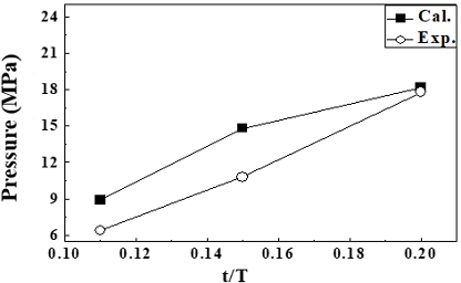
Fig. 6 shows the correlation between pressure at 0.2% circumferential strain and wall thinning thickness. A clear trend emerges: as flaw depth increases, the pressure required to achieve 0.2% strain decreases. For thickness ratios of 0.2, the error between experimental and analytical results was approximately 2.2%. However, this error margin exceeded 10% for thickness ratios below 0.2. This disparity can be attributed to factors not accounted for in the analysis, such as local buckling, which becomes increasingly prevalent during plastic deformation in real conditions.
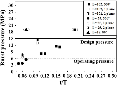
Fig. 7 shows the relationship between the thickness ratios of the wall thinned portion and internal pressure. The solid line and the dotted line mean design pressure (15 MPa) and operating pressure 6.2 MPa, respectively. In the case of a circumferential flaw, when the thickness ratio (t/T) of wall thinned portions of the pipes was smaller than 0.08, the pipes burst on the operating pressure and when the range from 0.08 to 0.18, the pipes burst on the designed pressure, and when it was over than 0.2, the pipe shows stability from not bursting and wasn’t damaged over the designed pressure. Yamaguchi12) was investigated burst pressure in pipes with square wall thinning by experiment and calcuation using FEA and API579 FFS-1, and is investigated the maximum allowable working pressure and the safety margin for burst pressure.
For single and double plane flaw, pipes with a thickness ratio below 0.08 did not rupture under operating pressure conditions. When the thickness ratio was between 0.08 and 0.12, all pipes failed before reaching the design pressure. Unlike the circumferential flaw, the 1 and 2 plane flaws didn’t burst below operating pressure when the thickness ratio was smaller than 0.08. This is because the shapes of the flaws were different from each other. Compared to circumferential flaws, the thinned areas of single and double plane flaw were smaller, resulting in a wider distribution of stress concentration. Despite identical flaw depth and length, stress distribution varied between pipe types due to differences in the size of the thinned area. While double plane flaw had a larger thinned area than single plane flaw, the single plane flaw exhibited lower burst pressures.
To investigate the cause of the differing burst pressures, a finite element method analysis was conducted to determine equivalent stress distribution within the thinned sections of single and double plane flaws. Fig. 8 shows that single plane flaw experienced higher equivalent stresses compared to double plane flaw under identical conditions.
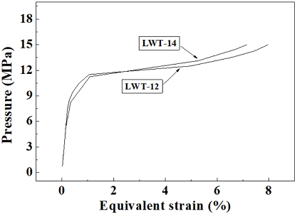
Fig. 9 compared the equivalent strain of single and double plane flaw under increasing pressure. The single plane flaw exhibited greater deformation than the double plane flaw at equivalent pressure levels. This indicates that the double plane flaw was able to distribute stresses more effectively, resulting in a higher burst pressure compared to the single plane flaw.
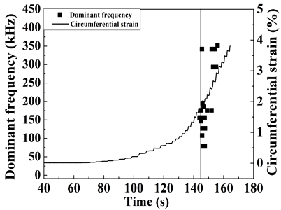
Acoustic Emission (AE) is the detection and analysis of elastic waves generated by the deformation or fracture of a solid material. Fig. 10 was carried out to determine the dominant frequency associated with the failure of wall thinned pipes to assess structural integrity. This shows the correlation between circumferential strain and dominant acoustic emission (AE) frequency over time. No AE signals were detected within the elastic strain region. However, once circumferential strain increased rapidly, indicating the onset of plastic deformation, AE signals detected. Wang et al.13) reported that detectable acoustic emission signals are generated during the yield in thin films. The dominant frequency of these signals is within the 78~195 kHz range, likely attributed to dislocation movement. Additionally, a higher frequency band of 292~351 kHz detected within the plastic strain region. These signals likely correspond to significant energy releases associated with dislocation interactions with grain boundaries or inclusions. The majority of AE signals were concentrated within the yield range rather than the plastic range. This suggests that dislocation movement is more frequently impeded by grain boundaries or hindered by dislocation pile-ups during the early stages of plastic deformation.
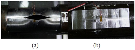
Fig. 11 shows the appearance of specimens LWT-1 and LWT-12 after test. The failure modes exhibited by these two specimens were different. LWT-12 showed a longitudinal split accompanied by a thin crack. In contrast, LWT-1 displayed a more severe failure mode, characterized by a wider, gaping longitudinal crack and significant bulging.
As showed in Fig. 5, both LWT-1 and LWT-12 exhibited rapid strain increases prior to failure. This rapid strain growth resulted in significant bulging and longitudinal tearing of the pipe. These results indicate that the failure mechanism for the SPPH380 pipe involved a plastic response with large plastic deformation within the thinned region.
4. Conclusions
This study investigated the failure behavior of carbon steel pipes with localized wall thinning subjected to internal pressure. The obtained results are as follows.
1) The burst pressure of pipes under internal pressure decreased with increase of depth, length, and area of the flaw.
2) Depending on the geometry of the thinned-wall, higher circumferential and axial stresses were applied, which results in a decrease in the burst pressure of the pipe, but there existed a limiting thickness which the pipe will not burst even under the design pressure.
3) The burst pressure of the pipe under internal pressure was dependent on the thinned-wall depth and length.
4) It was confirmed that the pipe could safely withstand internal pressure when the thickness ratio exceeded 0.2, indicating sufficient thickness.
5) AE signals were not detected within the elastic strain region, but once circumferential strain increased rapidly, indicating the onset of plastic deformation, AE signals detected. The dominant frequencies were obtained in the 78~195 kHz range, associated with dislocation motion, and in the 292~351 kHz range when pass inclusions and grain boundaries by dislocation pile-ups in plastic region.
― Nomenclature ―
| AE : | Acoustic emission |
| FEM : | Finite element method |
| LAWT : | Local allowable wall thickness |
| L : | Longitudinal length |
| Pb : | Burst pressure |
| R : | Outer diameter of pipe |
| T : | Thickness |
| d : | Thinned wall depth |
| t : | Thinned wall thickness |
| t/T : | Thickness ratio |
Author contributions
J. K. Lee; Conceptualization, Data curation, Investigation, Methodology, Resources, Writing-review & editing.
References
-
Y. M. Ferng and B. H. Lim, 2010, “Predicting the wall thinning engendered by erosion–corrosion using CFD methodology”, Nuclear Engineering and Design, 240(10), 2836-2841.
[https://doi.org/10.1016/j.nucengdes.2010.07.031]

-
Y. S. Lee, S. H. Lee and K. M. Hwang, 2016, “Cause analysis of flow accelerated corrosion and erosion-corrosion cases in Korea nuclear power plants”, The Corrosion Science and Technology of Korea, 14(4), 182-188.
[https://doi.org/10.14773/cst.2016.15.4.182]

-
R. Khan, A. H. I. Mourad, M. Wieczorowski, D. Damjanovic, W. Pao, A. Elsheikh and A. H. Seikh, 2024, “Erosion-corrosion failure analysis of the elbow pipe of steam distribution manifold”, Engineering failure Analysis, 160, 108177.
[https://doi.org/10.1016/j.engfailanal.2024.108177]

-
K. Hasegawa, T. Meshii and D. A. Scarth, 2011, “Assessment of piping field failures and burst tests on carbon steel pipes with local wall thinning using ASME section XI code case N-597-2”, Journal of Pressure Vessel Technology, 133(3), 031101.
[https://doi.org/10.1115/1.4002498]

-
C. Y. Kang, S. H. Kim and Y. T. Park, 2017, “Effect of Microstructure on the High Deformation Stability of Incoloy 825 Alloy”, Journal of the Korean Society for Power System Engineering, 21(2), 20-26.
[https://doi.org/10.9726/kspse.2017.21.2.020]

-
K. F. Tee and A. H. Wordu, 2020, “Burst strength analysis of pressurized steel pipelines with corrosion and gouge defects”, Engineering Failure Analysis, 108, 104347.
[https://doi.org/10.1016/j.engfailanal.2019.104347]

-
J. W. Kim, C. Y. Park and B. N. Kim, 2001, “Evaluation of local allowable wall thickness of thinned pipe subjected to internal pressure and bending moment”, Transactions of the Korean Society of Mechanical Engineers A, 25(1), 81-88.
[https://doi.org/10.22634/KSME-A.2001.25.1.81]

-
C. K. Oh, Y. J. Kim and C. Y. Park, 2009, “Effects of local wall thinning on net-section limit loads for pipes under combined pressure and bending”, Nuclear engineering and design, 239(2), 261-273.
[https://doi.org/10.1016/j.nucengdes.2008.10.019]

-
K. Takahashi, S. Tsunoi, T. Hara, T. Ueno, A. Mikami, H. Takada, K. Ando and M. Shiratori, 2010, “Experimental study of low-cycle fatigue of pipe elbows with local wall thinning and life estimation using finite element analysis”, International Journal of Pressure Vessels and Piping, 87(5), 211-219.
[https://doi.org/10.1016/j.ijpvp.2010.03.022]

-
M. Fahed, I. Barsoum, A. Alfantazi and D. Islam, 2020, “Burst pressure prediction of pipes with internal corrosion defects”, Journal of Pressure Vessel Technology, 142(3), 031801.
[https://doi.org/10.1115/1.4045886]

-
K. W. Nam and S. H. Ahn, 2004, “Fracture behaviors and acoustic emission characteristics of pipes with local wall thinning”, Key Engineering Materials, 270-273, 461-465.
[https://doi.org/10.4028/www.scientific.net/KEM.270-273.461]

-
A. Yamaguchi, 2014, “Investigation of Burst Pressure in Pipes With Square Wall Thinning by Using FEA and API579 FFS-1”, Pressure Vessels and Piping Conference, Paper No: PVP2013-97305, V007T07A014.
[https://doi.org/10.1115/PVP2013-97305]

-
X. Wang, E. K. Hermann Salje, X. Ding and J. Sun, 2014, “Detection of yield point behavior by acoustic emission in thin films”, materialstoday, 2, S535-S539.
[https://doi.org/10.1016/j.matpr.2015.07.341]


