An Investigation on Optimization of Vertical Hollow Hybrid Fin Heat Sinks with Horizontal Bases in Natural Convection
Abstract
This study investigates the optimization of vertical hollow hybrid fin heat sinks (HHFHSs) with horizontal bases in natural convection. The HHF is a hollow pin fin integrated with radial plate fins, and the HHFHS consists of the staggered array of HHFs and a horizontal base plate. The Nu correlations for the vertical HHF array were developed using a wide range of thermal data generated by CFD analysis and considering modified Ra, fin efficiency, and geometric parameters of the HHF. The optimization of the HHFHS was established by optimizing both the HHF using the least-material method and the fin spacing using the developed Nu correlations. It has been found that the optimal wall thickness of the HHF is a function of fin volume and structural perimeters. The investigation has proven that the optimal fin spacing of the HHFHS depends on the base length. The investigation has revealed that the thermal performance of the optimized HHFHS is superior to the optimized PFHS at a specific fin mass and a consistent base area.
Keywords:
Hollow Hybrid Fin, Natural Convection, Optimization, Correlation, Heat Sink1. Introduction
Cost-effectiveness and simplicity enable heat sinks to be an intensively-used thermal management solution in various applications.1) Drones, LED streetlights, and PV modules are typical thermally-managed electronics by vertical heat sinks with horizontal bases. Both optimum dimensions, allowing the maximum heat dissipation for the least material, and the prediction of thermal performance are crucial for natural convection heat sinks.2)
Rigorous investigations have focused on the optimization of the horizontal heat sinks with vertical base plates in natural convection. A single pin fin (PF) was optimized by Sonn et al.3) They employed the least-material optimization method. Rectangular, circular, and triangular horizontal fin arrays were optimized by Bar-Cohen et al.4) They utilized the least-material optimization method by considering manufacturability. Thermal behaviors of longitudinal and rectangular fin arrays were also explored under convection conditions.5)
Our research team explored the performance of the hollow hybrid fin (HHF) and the solid hybrid fin (SHF) heat sinks by comparing with classical PF heat sinks and the comparison was conducted at a fixed volume condition. Our research team developed the method predicting heat transfer around the hollow hybrid fin heat sink (HHFHS).6,7) As aforementioned, the optimization is a crucial goal for any types of heat sinks including the HHFHS. Hence, in this study, the primary objective is to investigate on the optimization of vertical HHFHSs with horizontal bases in natural convection. It should be noted that this paper is a considerably extended version of a preceding conference presentation.8)
First, this paper shows the CFD modelling of the HHF and PF arrays under natural convection to generate thermal data. Second, the paper presents the developed Nusselt number correlations of both HHF and PF arrays. Third, the paper shows the development process and the result of least-material optimization for a single HHF. Fourth, the paper presents the optimizing process of the fin spacing of the HHF and PF arrays. Last, the paper shows the thermal performance comparison between the optimized HHFHS and the PFHS.
2. Heat sink structure
This section explains the structure of the HHFHS and the PFHS. The HHFHS consists of a staggered HHF array and a base plate where the HHF has a hollow pin fin integrated with radial plate fins. The PFHS is a staggered pin fin array with a horizontal base plate.
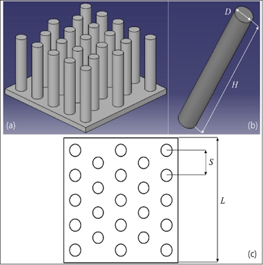
Fig. 1 and Fig. 2 schematically explain the structures of the HHFHS and the PFHS by showing the isometric views of single fins and heat sinks, and the top views of heat sinks. In Figs. 1 and 2, His the fin height, D is the pin fin diameter, Di is the internal fin diameter, Do is the external diameter, wp is the radial plate width, t is the thickness of theradial plate, and S is the fin spacing.
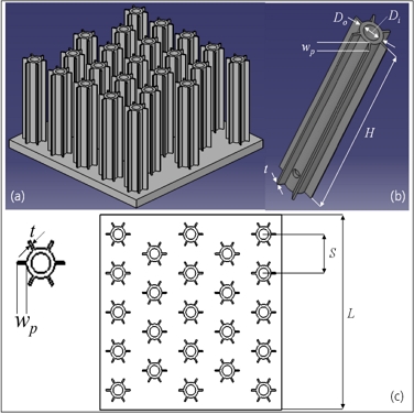
(a) The isometric view of the HHFHS, (b) the isometric view of the HHF, (c) the top view of the HHFHS
The base plate size of the heat sink is 75 × 75 × 5 mm, wp is 2 mm, and t is 0.5 mm. The number of radial plate fins is 6 for all the configurations. The heat sink material is aluminum 6063.
3. Computational analysis
3.1 Computational fluid dynamics
Computational fluid dynamics (CFD) analysis was conducted utilizing Ansys Fluent to generate a wide range of thermal data of the HHFHS and the PFHS to develop Nusselt number correlations using the data. For a wide range of data, 13 configurations of the HHFHS and 12 configurations of the PFHS were used, and the CFD analysis was conducted at four base temperatures of 50, 70, 90, and 120℃. The configuration variables are summarized in Table 1 where N denotes the number of fins.
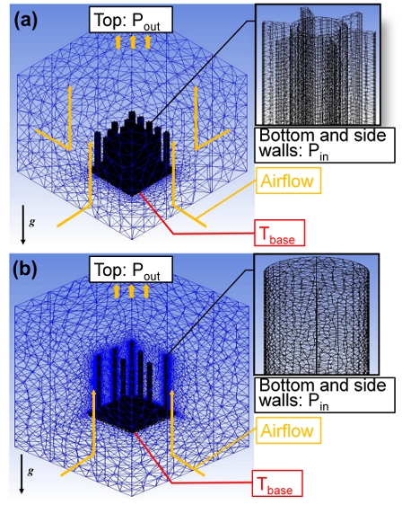
The meshed CFD models and boundary conditions for two types of heat sinks were shown in Fig. 3. For the PFHS, a quarter model was generated to reduce calculation time. About 25 million elements for the HHFHS and 5 million elements for the quarter model of the PFHS were used for mesh generation.
Tetra elements were used, the ambient temperature was selected as 25℃, the ambient pressure was selected as 1 atm, and the solid material was aluminum 6063.
The CFD analysis assumed the steady, incompressible, and laminar flow condition, and negligible thermal radiation. The governing equations for the CFD can be found in references,9) and the numerical conditions for the analysis are well shown in the preceding publications.6,7)
3.2 Nusselt number correlations
The Nusselt number, Nu, and the modified Rayleigh number, Ra' based on the fin spacing, S may describe natural convection around the fin array. They are written as follows
| (1) |
| (2) |
Where hfin is the convection heat transfer coefficient of the fin, kf is the thermal conductivity of the fluid, g is the gravity, L is the length of the base plate, γ is the volumetric thermal expansion coefficient, θb is the temperature difference between the base and the ambient, ν is the kinematic viscosity, and Pr is the Prandtl number. It should be noted again that Ra’S is the Rayleigh number modified by a base length, L. All the thermal properties are taken at the base temperature.
Nu correlations for the vertical HHF array and the vertical PF array were rigorously developed. For the development, the wide thermal data from CFD analysis for the various configurations, shown in Table 1, with for base temperatures were utilized, and the correlation structure10) was benchmarked. It should be noted that the correlation of Aihara10) is for the horizontal PF array.
The developed Nu correlations are shown in Eqn. (3) for the HHF array and Eqn. (4) for the PF array, respectively.
| (3) |
| (4) |
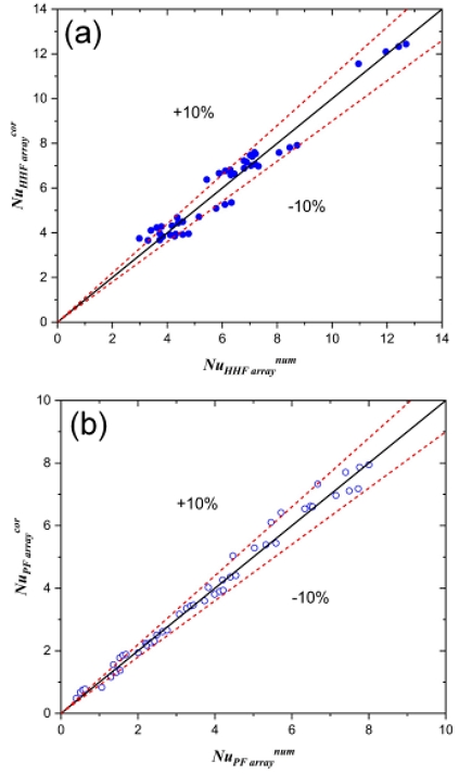
Figs. 4(a) and (b) show the comparison of the Nu numbers obtained by the CFD and the correlation for the HFF and the PF arrays. It is seen that prediction discrepancies of both Nu correlations are within typically 10%. The discrepancy average is seen to be 7.7%. These reasonable discrepancies may validate the Nu correlations.
4. Optimization
The optimization of heat sinks has two steps. Either a HHF or a PF is optimized by the least-material method, and then fin spacing is optimized to dissipate maximum heat rate for the base area.
4.1 Optimum HHF
The optimum pin fin diameter based on the least-material optimization [3] is expressed as
| (5) |
The general fin equation for the HHF is expressed as follows.
| (6) |
Where θb is the temperature difference between the fin base and ambient, hfin is the convection heat transfer coefficient of the fin, p is the perimeter of the fin, kfin is a fin thermal conductivity, Ac is the cross-sectional area of the fin, and H is the fin height. p and Ac are defined as
| (7) |
| (8) |
Where wp and t are the width and thickness of the radially-placed plate pin. In Eqn. (6), m is the eigenvalue of the 1-D fin equation2) and defined as
| (9) |
In this study, the HHF is optimized by determining optimum Di and Do. Heat dissipation from radially-placed plate fins are expected to be much smaller than the hollow pin fin. Hence, this investigation did not determine their optimum structures. Substituting Eqn. (9) into (6) and replacing the height as the volume, Eqn. (6) is rewritten as follows. Through this procedure, Eqn. (6) can be expressed as a function of only two variables, Di and Do, and it is written in Eqn. (10).
| (10) |
By differentiating Eqn. (10) by Do and Di and letting two differential equations be zero, following equations are obtained.
| (11) |
| (12) |
Substituting β = [(hfinp)/(kfinAc3)]0.5Vfin into Eqns. (11) and (12), they are re-expressed as
| (13) |
| (14) |
Considering Eqns. (13) and (14), a brief relation is obtained as
| (15) |
The calculated β, using the trial-error method, is about 1.4192. Using this value, the optimum Do-Di is expressed as
| (16) |
It is noteworthy that [(hfin{π(Do+Di)+12wp} Vfin2)/(kfinβ2)]1/3 should be greater than 6wpt because the Do-Di is always positive.
4.2 Optimum fin spacing
The total heat dissipation of the heat sink is determined by considering both heat dissipation of the fin array and the heat sink base. It is expressed as
| (17) |
Where hfin and hb are the convection heat transfer coefficients of the fin and the heat sink base, Afa is the surface area of the fin array, Aub is the net upper surface area of the heat sink base, i.e., the upper surface area of the heat sink base excluding the fin array footprint, ηfin is the fin efficiency, and θb is a base excess temperature to the ambient. In Eqn. (17), the fin efficiency, ηfin is defined as
| (18) |
hb is determined by considering the correlation for the heat transfer coefficient of an isothermal horizontal plate as follows.
| (19) |
The array heat transfer coefficient, ha, needed for optimization process, is defined as
| (20) |
Where Ab is a heat sink base area.
The heat sink base area was selected as 75×75 mm with a consistent base temperature of 70℃ for the optimization condition. The optimum fin spacing was determined by finding the maximum array heat transfer coefficient for various fin spacing values.
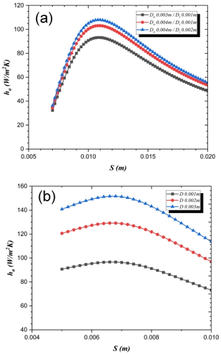
Eqns. (1) to (4) and (17) to (20) were utilized to evaluate ha for S and the results are plotted in Figs. 5(a) and (b). Figs. 5(a) and (b) show a noteworthy finding that for either the HHFHS or the PFHS, the optimum fin spacing value is consistent for each heat sink type despite various configurations.
This result suggests that the optimum S is only dependent on the length of the heat sink base. Thus, the optimum S is expressed as follows.
| (22) |
where U is defined as
| (23) |
4.3 Thermal performance
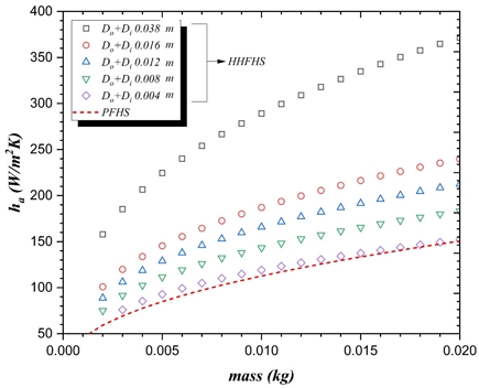
For the optimization, Eqn. (16) and (21) for the HHFHS, and Eqn. (5) and Eqn. (22) for the PFHS were utilized, and 75×75 mm base area and a base temperature of 70℃ were selected for the optimization condition. Fig. 6 shows a representative optimized performance, i.e., array heat transfer coefficient values, for the HHFHS and the PFHS as a function of fin mass. The fin mass ranges from 0.001 kg to 0.02 kg. The result shows that the optimum performance of the HHFHS depends on Do+Di. The result also reveals that much less materials could be used to manufacture the HHFHS than the PFHS for a specific thermal performance.
5. Conclusion
This study developed Nu correlations of the vertical HHF array and the PF array under natural convection. Consequently, the study investigated the optimization of the vertical HHFHS and the PFHS associated with the developed Nu correlations. The crucial study results are summarized as follows.
First, Nu correlations for the vertical HHF and PF arrays were rigorously developed by using CFD results. The Nu correlations contain the modified Ra and fin efficiency, and the average prediction discrepancies with CFD results are within 10%. Second, the HHF was optimized analytically by using the least-material method. As a result, the analytical expression of the optimum Do-Di for the HHF was obtained. Third, the optimum fin spacing for the HHFHS and the PFHS were determined by finding the maximum array heat transfer coefficient. It is seen that the optimum fin spacing depends on the base length. Last, it has been found that the thermal performance of the optimized HHFHS is superior to the optimized PFHS at a specific fin mass and a consistent base area.
― Nomenclature ―
| A : | Area [m2] |
| Ac : | Cross sectional area [m2] |
| D : | Diameter [m] |
| g : | Gravity [m/s2] |
| H : | Fin height [m] |
| HS : | Heat sink |
| h : | Heat transfer coefficient [W/m2K] |
| k : | Thermal conductivity [W/mK] |
| L : | Base length [m] |
| N : | Number of fins |
| Nu : | Nusselt number |
| P : | Perimeter [m] |
| Pr : | Prandtl number |
| q : | Heat transfer rate [W] |
| Ra : | Rayleigh number |
| Ra’s : | Modified Rayleigh number |
| S : | Fin spacing [m] |
| t : | thickness of plate fin[m] |
| U : | Parameter for optimum spacing [m] |
| V : | Volume [m3] |
| wp : | width of plate fin [m] |
Greek Symbols
| γ : | Volumetric expansion coefficient [1/K] |
| η : | Efficiency |
| θ : | Excess temperature to ambient [K] |
| ν : | Kinematic viscosity [m2/s] |
| ρ : | Density [kg/m3] |
Subscripts
| a : | Array |
| b : | Heat sink base |
| fa : | Fin array |
| fin : | Fin |
| i : | Internal |
| o : | External |
| ub : | Upper surface of base |
Acknowledgments
This research was supported by a Research Grant of Pukyong National University (2023).
Author contributions
W. Noh; Numerical analysis, Data acquisition, Writing-original draft. K. J. Kim: Conceptualization, Supervision, Writing-review & editing.
References
-
R. C. Chu, 2005, “The Challenges of Electronic Cooling: Past, Current and Future, Journal of Electronic Packaging”, 126, 491-500.
[https://doi.org/10.1115/1.1839594]

- A. D. Kraus and A. Bar-Cohen, 1995, Design and Analysis of Heat Sinks, U.S.A: Wiley-Interscience, 239-271.
-
A. Sonn and A. Bar-Cohen, 1981, “Optimum Cylindrical Pin Fin”, Journal of Heat Transfer, 103, 814-815.
[https://doi.org/10.1115/1.3244547]

- A. Bar-Cohen, M. Iyengar and S. Benjaafar, 2002, “Design for Manufacturability of Natural Convection Cooled Heat Sinks”, International Journal of Transport Phenomena, 4, 43-57.
-
A. Bar-Cohen and M. Jelinek, 1985, “Optimum Array of Longitudinal, Rectangular Fins in Convective Heat Transfer”, Heat Transfer Engineering, 6, 68-78.
[https://doi.org/10.1080/01457638508939633]

-
N. S. Effendi, S. S. G. R. Putra and K. J. Kim, 2018, “Prediction Methods for Natural Convection around Hollow Hybrid Fin Heat Sinks”, International Journal of Thermal Sciences, 126, 272-280.
[https://doi.org/10.1016/j.ijthermalsci.2018.01.002]

-
H. H. Yang, W. Noh, S. Jamilah and K. J. Kim, 2023, “An Investigation on Predicting Natural Convection around Hollow Hybrid Fin Arrays”, Journal of Power System Engineering, 27(1), 14-21.
[https://doi.org/10.9726/kspse.2023.27.1.014]

-
W. Noh and K. J. Kim, 2023, “Optimization of Hollow Hybrid Fin Heat Sinks under Natural Convection”, IEEE 29th Therminic, Sep., 2023, Budapest, Hungary.
[https://doi.org/10.1109/THERMINIC60375.2023.10325900]

- K. A. Hoffmann and S. T. Chiang, 1998, Computational Fluid Dynamics Volume I, Third ed., Engineering Education System, Wichita, KS.
-
T. Aihara, S. Maruyama and S. Kobayakawa, 1990, “Free Convective/Radiative Heat Transfer from Pin-Fin Array with a Vertical Base Plate (General Representation of Heat Transfer Performance)”, International Journal of Heat and Mass Transfer, 33, 1223-1232.
[https://doi.org/10.1016/0017-9310(90)90253-Q]


