Development of a Lightweight Brake Piston for Passenger Car
Abstract
Recently, to respond to strengthened regulations of each country, automobile manufacturers are increasingly interested in weight reduction when developing each part. As a result, related companies strive to reduce the weight by substituting existing materials or changing manufacturing methods, regardless of the body, chassis, and powertrain. In this study, the piston, a part of the disc brake made of cast iron, was changed to plastic material, and the performances were investigated by the numerical analysis and test. The development of the new brake piston was conducted through the base design, injection analysis, static strength analysis, and durability tests. The material of the new brake piston is polyphenylene sulfide (PPS), and the optimal process conditions were suggested by applying the design of experiments in consideration of the deviation of shrinkage rate, which is one of the main performances in the injection process. In addition, this research performed the strength analysis of the piston using FE analysis and evaluated the durability performance through the tests. The weight of the final proposed piston was reduced by 80.2% from the existing 700 g to 138.7 g. The Moldex3D, an injection analysis program, and the Abaqus, a structural analysis program, were used for CAE in this process.
Keywords:
Weight Reduction, Brake Piston, Injection Analysis, Design of Experiments (DOE), Durability1. Introduction
In recent new car developments, eco-friendly vehicles such as electric vehicle (EV), hybrid vehicle (HEV), plug-in HEV(PHEV), and fuel cell vehicle (FCV) are gaining popularity in response to stricter regulations.1) However, despite the development of eco-friendly cars, it is expected that the proportion of internal combustion engine (ICE) cars cannot be ignored until 2050.2) Whether it is an eco-friendly vehicle or an ICE vehicle, the demand for weight reduction in automobile parts increases. This trend is because the vehicle's weight is directly related to harmful gas emissions and energy efficiency. Therefore, parts manufacturers are also making a lot of effort from the development stage, such as changing materials and developing manufacturing methods for weight reduction. In response to this trend, some parts have target weights set in grams during the prototype design stage. A development procedure for weight reduction of the piston, a disc brake component, was presented in this research.
A disc brake consists of a disc rotor, caliper, piston, cylinder, hub, and pad. The disc brake principle is that when a driver presses the brake pedal, the hydraulic pressure in the brake line pushes the piston inside the caliper, and the pad comes into contact with the disc rotor, thereby generating friction and braking. The disc's material has been changed from cast iron or steel to aluminum, titanium, ceramic, etc., and the material of the caliper has been changed from cast iron to aluminum. However, the piston is still mostly made of cast iron. In this study, the piston's weight was reduced by changing the material of the piston to plastic material. For this, the process optimization, strength analysis, and durability tests were performed.
The weight reduction of the brake system is made mainly with the disc, pad, and caliper. The discs are changing from cast iron to various types of materials. The disc made of the modified material must meet the criteria for friction, wear, and thermal properties. Saravanan et al.4) proposed a 10% cenosphere-reinforced aluminum alloy (AA) 6063 composite as the most suitable lightweight material for discs. In addition, Shanker et al.5) show that MMCs (Metal Matrix Composites) is advantageous for weight reduction and improvement of strength and hardness compared to other disc materials. Also, Topouris and Tirovic6) used topology and shape optimization to reduce the weight of monobloc cast iron brake discs. In the case of caliper parts, Inoue et al.7) applied shape optimization, Ugemuge and Das,8) and Tyflopoulos and Lien9) applied topology optimization to achieve weight reduction.
As mentioned above, many attempts to lighten the disc and caliper in disc brakes, but there are not many cases of lightening the brake piston. In this study, a weight reduction is attempted by changing the existing cast iron piston brake to PPS. The PPS, a crystalline thermoplastic, has a similar strength to metals and has excellent price competitiveness.10-11) The PPS resin is a crystalline polymer with a structure in which sulfur is bonded to a benzene ring, has a usable temperature of 218°C, and is a material with excellent chemical resistance without a solvent that can be dissolved at room temperature12). On the other hand, it has the disadvantage of low dimensional precision due to high volumetric shrinkage.10-12) This disadvantage is a characteristic of crystalline resin, and the shrinkage rate varies depending on residual stress and fiber orientation and is not easy to predict. In addition, since this variation of the shrinkage rate leads to decreased product quality, a process to uniformly minimize the shrinkage rate is required.
In this study, the performances of injection, strength, and durability of the piston were investigated for changing the piston material from cast iron to PPS. The injection process of the PPS with excellent mechanical properties but significant shrinkage deviation and non-uniformity in the development process of the brake piston was analyzed and optimized using the DOE. The DOE was applied to find the sensitivity of the process variables and the optimal design variables. In this step, the use of orthogonal array and analysis of variance (ANOVA) are included. After finding the optimal injection process parameters, the static strength was considered through the FE analysis. In addition, the durability performance was checked at room temperature and low temperature. The final proposed PPS-disc brake piston resulted in a weight reduction of about 80.2% compared to the cast iron material. In this study, the Moldex3D was used for injection analysis, the Abaqus was used for structural analysis, and the test machine from a component manufacturer was used for the durability tests.
2. Summary of the development process
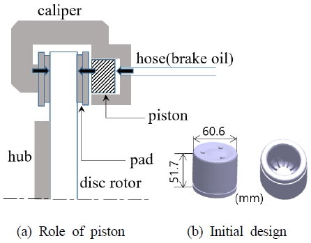
In disc brakes, when a driver presses the pedal, the force is increased through the booster, and this force presses the master cylinder, and the hydraulic pressure generated at this time pushes the piston. The piston then moves the pads against the disc rotor, creating friction and generating braking force. The working principle of the disc brake is shown in Fig. 1 (a), which shows only the upper part of the cross-section of the disc brake, and Fig. 1 (b) shows the initial CAD model of the piston.
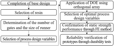
The overall development process of the brake piston under development is shown in Fig. 2. First, the shape is based on the existing cast iron made piston. Then, the PPS having excellent thermal stability, high toughness, inherent flame resistance, good chemical resistance, high mechanical strength, and dimensional stability was selected as the resin. The dimension of the runner was determined using the empirical formula, and the number and location of gates were determined by trial and error and numerical analysis. The runner size, packing time, melt temperature, filling time, and mold temperature, which are expected to affect the deviation of shrinkage rate as a characteristic value, were selected as process variables. Then, by applying DOE, the factors affecting the deviation of shrinkage rate were analyzed and the optimal levels were determined. After the process optimization, the strength performance was investigated through FE analysis, and the durability tests were performed at room temperature and low temperature with the prototypes.
3. Plastic molding injection analysis and DOE
The Moldex3D, an injection analysis program, was used for the process optimization of the lightweight brake piston. The runner size, filling time, packing time, melt temperature and mold temperature were selected as the process variables, and their effects on the deviation of shrinkage rate were evaluated using DOE, and the optimal levels were suggested.3)
3.1 Considerations on the number of gates and the size of runner
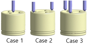
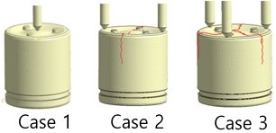
A gate is usually determined by considering the thickness of the product, weld line, clamping force according to flow length, flow pattern, and residual stress. Taking these into consideration, the number and location of the gate of the piston brake were examined in three cases as shown in Fig. 3. In Fig. 3, Case 1, Case 2, and Case 3 are the models with 1, 2, and 3 gates, respectively.
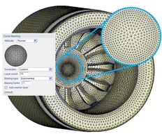
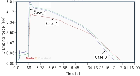
The numerical model using the Moldex3d was made as Fig. 4. For the mesh in Moldex3d, “templates” was set to “custom”, “Layer count” was set to 10, “Biasing type” was set to “Exponential”, and “Biasing factor” was set to -1. Considering the clamping force curves shown in Fig. 5, the maximum value in the curve of the Case 1 is the lowest, thus the Case 1 is the most advantageous. The number and size of weld lines for each case are shown in Fig. 6. It can be seen that the first case is optimal considering the weld lines being generated in the second and third cases. Reflecting these results, the number of gates was determined as one. The range of runner diameter, d was determined to be 8 to 12 mm using empirical data and Eq. (1).3)
| (1) |
Where w is the weight(g) and L is the length(mm).
3.2 Application of DOE and results
A shrinkage rate is the ratio of the decrease in volume of a polymer that occurs when changing from a molten state to a cooled state. The shrinkage rate has a significant impact on the final size and shape of the product. The deviation in shrinkage rate across the entire area results in product defects. Therefore, in the DOE of this study, the standard deviation(SD) of shrinkage rate is selected as a characteristic, and this is calculated from Moldex3d.
The process variables considered to calculate shrinkage rate are runner diameter(x1), packing time(x2), melt temperature(x3), filling time(x4), and mold temperature(x5). The level of each process variable was set to three and is summarized in Table 1. The x3 and x5 listed in Table 1 are the average temperatures in the steady state, which are automatically calculated by the Modelx3d. The L18 orthogonal array suggested by G. Taguchi was selected for the DOE considering the number of factors and levels. In this brake piston within the ranges of process variables in Table 1, minimizing the variation in shrinkage rate, rather than the shrinkage rate itself, has a greater impact on product quality. Therefore, in this study, the SD in shrinkage rate was considered as a performance characteristic.
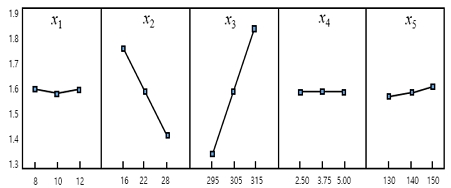
The L18 orthogonal array has the characteristic that the interactions between each factor are evenly distributed among other factors.13) Each factor is placed in five columns excluding the first two columns of the L18 orthogonal table. The orthogonal array arranging the values for each level of each factor is shown in Table 2. The last column was assigned for SD selected as the characteristic value. The main effect of each process variable determined from the ANOM (analysis of means) is summarized in Fig. 7. From these results, it can be seen that the packing time, melt temperature, and mold temperature have a greater influence on shrinkage rate deviation than the runner size and filling time. The ANOVA table with original process variables a=0.05 is shown as Table 3. Looking at Table 3, x1 and x4 are not significant. Therefore, the ANOVA table pooling x1 and x4 is shown in Table 4. It can be seen that the influence on SD is greater in the order of x3, x2, and x5.
From the ANOM, the optimum levels of x1, x2, x3, x4, and x5 are selected as 2, 3, 1, 2, and 1 specified in Table 1. These levels correspond to 10mm, 28s, 295℃, 3.75s, and 130℃ for the runner size, packing time, melt temperature, filling time, and mold temperature, respectively. The point estimator of SD at the optimum levels was calculated as,
| (2) |
Where the first subscript of x indicates the order of the design variables, the second subscript indicates the optimal level of the xi variable, and μ indicates the overall mean of SD. The value of the estimator is 1.145, which is very close to the value of Exp. No. 14 in Table 2.
4. Static strength analysis and durability test
The static strength performance of the brake piston was predicted through the FE analysis. For the analysis, the commercial program, the Abaqus was used. Loading conditions and strength standards complied with the manufacturer's specification.
4.1 Static strength analysis
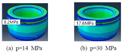
For the strength analysis of the brake piston, all degrees of freedom in the area in contact with the brake pad were constrained, and internal pressures of 14 MPa and 30 MPa were applied, respectively. These internal pressures are the design loads used by the manufacturer. The ultimate strength of PPS, the material of this brake piston, is 190 MPa, and this value is set by the manufacturer as the allowable stress.
As shown in Fig. 8, when internal pressures of 14 MPa and 30 MPa were applied to the piston, the maximum stresses were calculated to be 8.2 MPa and 17.6 MPa, respectively. All of these maximum stress values satisfy the criterion.
4.2 Durability test
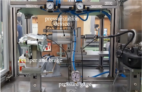
The durability test is performed with the brake assembly rather than the brake piston alone. Therefore, the brake assembly on which the brake piston under development is mounted was fixed to the test machine as shown in Fig. 9 and the durability tests were performed. The durability tests for brake assembly were performed under room and cold temperatures, respectively. The room temperature is set at 25℃, and the low temperature is set at -30℃. The 500,000 and 70,000 cycles with the pressure of 0~7 MPa are loaded on the test machine for the room and cold temperatures, respectively. After this process, there must be no leakage and the change of stroke should be below the criterion.
All the requirements for the durability tests were satisfied, and Fig. 10 shows that three samples measured the pressure leak assessment and stroke change after the durability tests.
5. Conclusions
The brake piston material was replaced with cast iron to PPS to reduce the weight of the brake. For its developing stage, injection performance, strength, and durability were investigated using CAE and test. Through this, the following conclusions were obtained.
1) The weight of the existing cast iron piston was 700 g, but this was changed to PPS and a 138.7 g piston was presented. This resulted in a weight reduction of 80.2%.
2) The number and location of gates were selected through the injection analysis considering the weld line and clamping force. In addition, using the DOE method, the influence of runner size, filling time, pack time, melt temperature, and mold temperature on the variation in shrinkage rate was evaluated and the optimal level for each factor was determined. That is, the process conditions for runner size, filling time, pack time, melt temperature, and mold temperature were determined as 10mm, 28s, 295℃, 3.75s, and 130℃, respectively.
3) The strength performance of the piston made of PPS was investigated using the FE analysis, and the results that satisfied the criterion were obtained. In addition, the durability tests were performed by attaching the developed piston to the existing brake assembly. This durability tests were conducted at room temperature and low temperature, respectively, and as a result, there were no pressure leakage or stroke changes.
Acknowledgments
This work was supported by the Dong-A University research fund. The authors would like to thank ETS-SOFT for their great assistance in using the Moldex3D. This study includes some of the results of Jang master thesis(Ref. No. 3).
Author contributions
S. H. Jang; Numerical analysis, collecting data, and writing-original draft. K. H. Lee; Conceptualization, supervision, and writing-review & editing.
References
-
J. W. Choi, S. H. Han and K. H. Lee, 2021, “Structural Analysis and Optimization of an Automotive Propeller Shaft”, Advances in Mechanical Engineering, 13(10), 1-11.
[https://doi.org/10.1177/16878140211053173]

- IEA. Global EV outlook 2020. Technology report, 2020, 87-88. (https://iea.blob.core.windows.net/assets, )
- S. H. Jang, 2018, “Process Optimization for Injection-Type Brake Piston Uniform Shrinkage”, Master Thesis, Dong-A University, Korea.
-
V. Saravanan, P. R. Thyla and S. R. Balakrishnan, 2016, “A Low Cost, Light Weight Cenosphere–Aluminium Composite for Brake Disc Application”, Bulletin of Materials Science, 39(Feb), 299–305.
[https://doi.org/10.1007/s12034-015-1134-2]

-
P. Shiva Shanker, 2018, “A Review on Properties of Conventional and Metal Matrix Composite Materials in Manufacturing of Disc Brake”, Materials Today: Proceedings, 5(2), 5864-5869.
[https://doi.org/10.1016/j.matpr.2017.12.184]

-
T. Stergios and T. Marko, 2019, “Design Synthesis and Structural Optimization of a Lightweight, Monobloc Cast Iron Brake Disc with Fingered Hub”, Engineering Optimization, 51(10), 1710-1726.
[https://doi.org/10.1080/0305215X.2018.1542692]

-
H. Inoue, K. Hashimoto and Y. Kumemura, 2015, “Study of Development Technology of Brake Caliper Which Balances Preventing Squeal with Weight Reduction”, SAE Technical Paper 2015-01-2688.
[https://doi.org/10.4271/2015-01-2688]

-
M. Ugemuge and S. Das, 2020, “Topology Optimisation of Brake Caliper”, SAE Technical Paper 2020-01-1620, 2020.
[https://doi.org/10.4271/2020-01-1620]

-
E. Tyflopoulos, M. Lien and M. Steinert, 2021, “Optimization of Brake Calipers Using Topology Optimization for Additive Manufacturing”, Applied Sciences, 11(4), 1437.
[https://doi.org/10.3390/app11041437]

-
A. S. Rahate, S. Ashok, K. R. Nemade and S. A. Waghuley, 2013, “Polyphenylene Sulfide (PPS): State of the Art and Applications, Reviews in Chemical Engineering”, 29(6), 471-489.
[https://doi.org/10.1515/revce-2012-0021]

-
Z. Peiyuan, T. Abbas, S. Mohammadali, F. Joseph and B. Farid, 2019, “Overall Investigation of Poly(Phenylene Sulfide) from Synthesisand Process to Applications-A Reivew”, Macromolecular Materials and Engineering, 304(5), 1-27.
[https://doi.org/10.1002/mame.201800686]

-
C. Um, D. Jung, S. Y. Yu, S. S. Lee and H. W. Lee, 2020, “Study on Physical Properties of Polyphenylene Sulfide Composites with Variothermal Mold Temperatures”, Polymer-Korea, 44(6), 798-803.
[https://doi.org/10.7317/pk.2020.44.6.798]

- G. S. Peace, Taguchi Methods: A Hands-On Approach, 1995, Addison-Wesley Publishing Company, Massachusetts.

