
R134a 대체냉매인 R152a, R1234yf, R290을 적용한 차량용 히트펌프시스템의 성능 비교

초록
전기자동차에서는 엔진에서의 발생열을 사용할 수 없고 PTC 히터를 사용하면 주행거리가 급격히 떨어져 히트펌프 시스템은 전기자동차뿐만 아니라 하이브리드 자동차에서는 필수이다. 이에 따라 차량용 히트펌프 시스템에 대한 다양한 연구들이 진행되고 있으며, 히트펌프 시스템에 R134a가 많이 사용되었는데 이 냉매의 대체 냉매로서 R152a, R1234yf, R290 등이 각광받고 있다. 따라서 본 연구에서는 차량용 히트펌프 시스템의 냉매로 R134a, R152a, R1234yf, R290을 적용하여 히트펌프 시스템의 성능에 영향을 미치는 과열도, 과냉도, 증발온도, 응축온도에 따른 냉매에 따른 비교를 분석하였다. 그 주요 결과는 다음과 같다. 성능계수 측면에서는 R152a가 가장 유리하였고, 냉매 충전율 측면에서는 R152a와 R290이 유리하였다.
Abstract
In electric vehicles, the heat generated from the engine cannot be utilized, and the driving range decreases sharply if a PTC heater is used, so the heat pump system is an essential not only in electric vehicles but also in hybrid vehicles. Accordingly, various studies on vehicle heat pump systems are being conducted, and R134a has been widely used in heat pump systems, but R152a, R1234yf, and R290 are gaining attention as alternative refrigerants. Therefore, in this study, R134a, R152a, R1234yf, and R290 were applied as refrigerants in vehicle heat pump systems, and a comparison was analyzed according to the superheating, subcooling, evaporation temperature, and condensation temperature that affect the performance of the heat pump system. The main results are as follows. In terms of the coefficient of performance, R152a was the most advantageous, and in terms of the refrigerant charge rate, R152a and R290 were advantageous.
Keywords:
Alternative Refrigerants, R134a, R152a, R1234yf, R290키워드:
대체냉매1. 서 론
차량용 난방을 위해 내연기관 차량에서는 엔진에서 발생하는 열을 난방에 활용하였다.1) 그래서 반응속도가 빠르고 대용량의 히터를 구현할 수 있다는 장점이 있으나 구조가 복잡하고 큰 공간이 필요하다는 단점으로 인하여 PTC 히터 방식이 채택되어 사용되고 있다. 그러나 PTC 히터 방식이 사용하기 편리하나 전기에너지를 저항으로 열을 발생시키기 때문에 난방 효율이 지극히 떨어진다는 한계가 있다. 이러한 문제점들에 대한 해결책으로 히트펌프 시스템이 최근 대두되고 있다.
특히, 전기자동차에서는 예전처럼 엔진에서 발생하는 열을 활용할 수도 없고, 전기로 주행하는 전기차에서 PTC 히터를 사용하면 주행거리가 급격히 떨어지기 때문에 히트펌프 시스템은 전기자동차뿐만 아니라 하이브리드 자동차2)에서도 필수라고 할 수 있다.
이에 따라 차량용 히트펌프 시스템에 대한 냉매 충진량3) 등 다양한 연구4-8)가 진행되고 있다. 또한 차량 냉방용으로 R134a가 사용되었지만 온실가스 배출량이 높아 친환경적인 냉매들에 대한 연구들이 활발히 진행되고 있다.9) 대표적인 대체냉매로 R152a, R1234yf, R290 등이 있으며, 이 대체냉매를 함께 비교한 연구는 없다.
따라서 본 연구에서는 차량용 히트펌프 시스템에 R134a와 대체냉매인 R152a, R1234yf, R29010-12)을 적용하여 히트펌프 시스템의 성능계수(COP)와 질량유량에 영향을 미치는 요인들(과열도, 과냉도, 증발온도, 응축온도)의 변화에 따른 냉매별 비교 및 분석을 하고자 한다.
2. 수치 해석
본 논문에 적용한 냉매의 열역학적 물성치와 성능 분석은 EES(Engineering Equation Solver, V10.561, 2018) 소프트웨어를 사용하였고, 차량용 히트펌프 시스템의 성능 분석을 위해 다음과 같이 가정하였다.
- 히트펌프 시스템의 압축기 내 냉매는 단압축과정이고, 기계효율(ηm)은 통상의 경우를 예상하여 0.8이라 가정한다.
- - 열교환기(증발기, 응축기)와 배관 내 냉매 압력강하와 열손실은 무시한다.
- - 히트펌프 시스템의 팽창밸브 내 냉매는 단열팽창인 등엔탈피과정이다.
- - 운동에너지의 변화는 없는 것으로 가정한다.
- 증발열량은 동일한 비교를 위해 3.86 kW로 고정한다.
- - 열교환기와 배관 내 냉매 압력강하와 열손실은 무시하므로 증발온도와 응축온도는 일정하다.
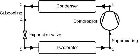
Fig. 1은 본 연구에서 적용하는 히트펌프 시스템의 개략도이고, 분석에 필요한 식들은 Table 1에 정리하였다.
Schematic diagram of heat pump system

Balance formula for each component of heat pump system
여기서, QE는 증발열량, QC는 응축열량, WCOM은 압축일량이며, 는 질량유량, h는 엔탈피, ΔTSUB는 과냉도, ΔTSUP는 과열도를 나타낸다. 히트펌프 시스템의 COP는 증발열량과 압축일량으로부터 다음과 같이 계산한다.
| (1) |
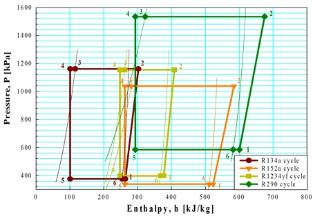
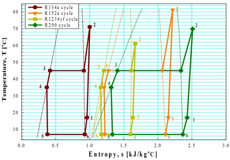
Fig. 2와 3에서 냉매에 따른 히트펌프 시스템의 P-h 선도와 T-s 선도를 나타내었다.
P-h diagram of heat pump system with respect to refrigerants
T-s diagram of a heat pump system with respect to refrigerants
차량용 냉방 및 난방할 때의 증발온도/응축온도는 각각 7/45℃, -7/41℃를 기준13)으로 하기에 본 연구에서는 냉방일 때 Table 2와 같은 조건 하에서 히트펌프 시스템에 영향을 미치는 증발온도, 과열도, 응축온도, 과냉도의 변수들에 대한 냉매별 영향을 비교하여 분석하고자 한다.
Analysis conditions of heat pump system
3. 결과 및 고찰
3.1 과열도와 과냉도에 따른 영향
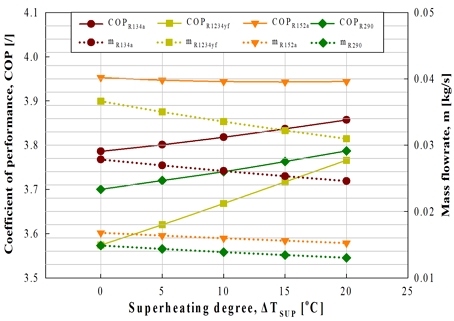
Fig. 4는 Table 2에서와 같이 일정한 표준 조건하에서 과열도를 0℃에서 20℃까지 5℃씩 증가시킬 때 히트펌프 시스템의 COP와 질량유량의 변화를 나타낸 것이다.
Variation of COP and mass flowrate with respect to superheating degree
COP의 경우, R152a, R134a, R290, R1234yf 순으로 높고, Table 3과 4을 살펴보면, 과열도가 5℃씩 증가함에 따라 R134a는 0.40~0.52%씩 증가하였고, R152a는 0.03~0.15%씩 감소하다가 0.03% 증였고, R152a는 0.03~0.15%씩 감소하다가 0.03% 증가하였다. R1234yf는 1.29~1.34%씩 증가하였고, R290은 0.54~0.64%씩 증가하였다. 여기서, 냉매별로 COP가 소량씩 증가한 이유는 과열도 증가에 따라 압축기 입출구의 엔탈피 차(h2-h1)가 증가하지만 증발기 입출구의 엔탈피 차(h1-h5)가 더 크게 증가하기 때문인 것으로 판단된다.
Enthalpy difference of inlet and outlet in evaporator with respect to superheating degree
Enthalpy difference of inlet and outlet in compressor with respect to superheating degree
과열도가 증가할수록 Table 5에서 알 수 있듯이 R152a는 과열도 약 15℃까지 COP가 감소하다가 이후에 증가하였고, R290은 R134a보다 미소하게 증가율이 크고, R1234yf는 R134a 대비 2.58~3.225배 증가율이 크다.
COP variation of R134a, R152a, R1234yf and R290 by increasing of superheating degree
질량유량의 경우에는 R1234yf, R134a, R152a, R290 순서로 높았고, 과열도가 5℃씩 증가함에 따라 R134a는 2.92~3.20%씩 감소하였고, R152a는 2.31~2.50%씩 감소하였다. R1234yf는 3.88~4.40%씩 감소하였고, R290은 3.13~3.43%씩 감소하였다. 이는 증발열량을 3.86 kW로 고정하였을 때 과열도의 증가에 따라 증발기 입구의 엔탈피(h5)는 일정하지만 증발기 출구의 엔탈피(h1)가 증가하여 증발기 입출구의 엔탈피 차(h1-h5)가 증가하기 때문인 것으로 판단된다.
Fig. 5는 일정한 표준 조건 하에서 과냉도가 0℃에서 20℃까지 5℃씩 증가함에 따른 히트펌프 시스템의 COP와 질량유량의 변화를 나타낸 것이다.
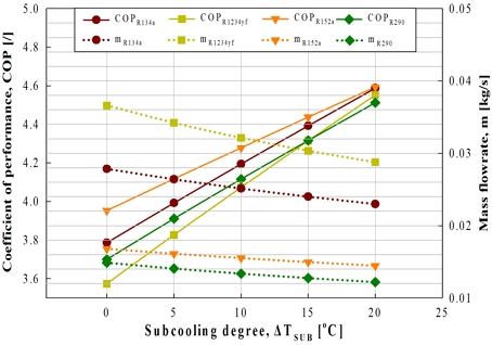
Variation of COP and mass flowrate with respect to subcooling degree
COP의 경우, R152a, R134a, R290 순으로 높고, R1234yf는 과냉도가 약 15℃ 미만일 때는 R290 보다 작았고, 약 15℃ 이상에서는 R290보다 높았다. Table 6에서 알 수 있듯이 과냉도가 5℃씩 증가함에 따라 R134a는 4.44~5.44%씩, R152a는 3.52~4.15%씩, R1234yf는 5.49~7.08%씩, R290은 4.54 ~5.70%씩 증가하였다. 여기서, 냉매별로 COP가 증가한 이유는 Table 7에서와 같이 과냉도 증가에 따라 압축기 입출구의 엔탈피 차는 일정하지만 증발기 입출구의 엔탈피 차가 증가하기 때문인 것으로 판단된다. 과냉도가 증가할수록 R152a는 R134a보다 증가율이 작고, R1234yf와 R290은 R134a보다 증가율이 크다.
Enthalpy difference of inlet and outlet in evaporator with respect to subcooling degree
Enthalpy difference of inlet and outlet in compressor with respect to subcooling degree
질량유량의 경우에는 R1234yf, R134a, R152a, R290 순으로 높았고, 과냉도가 5℃씩 증가함에 따라 R134a는 4.25~5.14%씩, R152a는 3.41~3.99%씩, R1234yf는 5.21~6.61%씩, R290은 4.32~5.38%씩 감소하였다. 이는 증발열량이 3.86 kW로 일정하기 때문에 과냉도의 증가에 따라 증발기 출구의 엔탈피는 일정하지만 증발기 입구의 엔탈피가 감소하여 증발기 입출구의 엔탈피 차가 증가하기 때문인 것으로 판단된다.
3.2 증발온도와 응축온도에 따른 영향
Fig. 6은 일정한 표준 조건 하에서 증발온도를 -12℃에서 7℃까지 4~5℃씩 증가에 따른 히트펌프 시스템의 COP와 질량유량의 변화를 나타내었다.
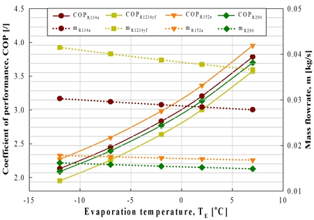
Variation of COP and mass flowrate with respect to evaporation temperature
COP의 경우, R152a, R134a, R290, R1234yf 순으로 높고, 증발온도가 5℃씩 증가할 때 R134a는 14.77~18.13%씩, R152a는 14.19~17.54%씩, R1234yf는 15.78~18.97%씩, R290은 14.70~18.02%씩 증가하였다. 여기서, 냉매별로 COP가 증가한 이유는 증발온도 증가에 따라 압축기 입출구의 엔탈피 차는 감소하고, 증발기 입출구 엔탈피 차가 증가하기 때문에 크게 증가한 것으로 판단된다.
과냉도가 증가할수록 R152a와 R290은 R134a 보다 증가율이 작고, R1234yf는 R134a보다 증가율이 크다.
질량유량의 경우에는 R1234yf, R134a, R152a, R290 순서로 높고, 증발온도가 4~5℃씩 증가함에 따라 R134a는 1.73~2.31%씩, R152a는 1.22~1.57%씩, R1234yf는 2.53~3.40%씩, R290은 1.68~2.29% 씩 감소하였다. 이는 증발온도의 증가에 따라 과열도 증가에 따른 영향에서와 동일하게 증발기 입구의 엔탈피(h5)는 일정하지만 증발기 출구의 엔탈피(h1)가 증가하여 증발기 입출구의 엔탈피 차(h1-h5)가 증가하기 때문인 것으로 판단된다.
Fig. 7은 일정한 표준 조건 하에서 응축온도를 30℃에서 50℃까지 5℃씩 증가에 따른 히트펌프 시스템의 COP와 질량유량의 변화를 나타내었다.
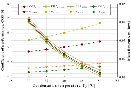
Variation of COP and mass flowrate with respect to condensation temperature
COP의 경우, R152a, R134a, R290, R1234yf 순으로 높고, 응축온도가 5℃씩 증가함에 따라 R134a는 15.11~20.26%씩, R152a는 14.24~19.76%씩, R1234yf는 16.26~20.90%씩, R290은 15.38~20.42%씩 감소하였다. 여기서, 냉매별로 COP가 감소한 이유는 응축온도 증가에 따라 압축기 입출구의 엔탈피 차는 증가하고, 증발기 입출구 엔탈피 차는 감소하기 때문에 크게 감소한 것으로 판단된다.
응축온도가 증가할수록 R152a는 R134a보다 감소율이 소폭 작고, R1234yf와 R290은 R134a보다 감소율이 소폭 크다.
질량유량의 경우에는 R1234yf, R134a, R152a, R290 순서로 높았고, 응축온도가 5℃씩 증가함에 따라 R134a는 4.75~5.89%씩, R152a는 3.75~4.41%씩, R1234yf는 5.93~7.73%씩, R290은 4.87~6.12%씩 증가하였다. 이는 응축온도 증가에 따라 증발기 입출구의 엔탈피 차는 감소하고 압축기 입출구의 엔탈피 차는 증가하기 때문인 것으로 판단된다.
4. 결 론
차량용 냉매로서 R134a의 대체냉매로 대두되고 있는 R1234yf, R152a, R290을 비교하였다. 그 결론은 다음과 같다.
1) COP 측면에서 냉매별 끓는점/임계온도의 영향으로 R152a(-24.02℃/113.3℃)는 R134a(-26.07℃/101.1℃)보다 다소 유리하고, R1234yf(-29.49℃/94.70℃)와 R290(-42.11℃/96.74℃)은 R134a보다 다소 불리하다. 특히, 과열도가 높을수록 엔탈피값 변화비율에 의해 R1234yf가 R134a 대비 2.58~3.225배 증가율이 높아 유리하다.
2) 질량유량 측면에서 냉매별 밀도로 인하여 R1234yf는 R134a보다 불리하고, R152a와 R290은 R134a 보다 유리하다.
Author contributions
M. J. Jeon; Conceptualization, Data curation, Investigation, Methodology, Software, Validation, Visualization, Writing-original draft, Writing-review & editing
References
- https://brunch.co.kr/@1212ac31a500435/174, .
- D. W. Lee, M. W. Kim, H. J. Lee and D. W. Hwang, 2024, “Study on Feasibility of Applying an Economical Heat-pump System for Hybrid Electric Vehicle”, The Korean Society of Automotive Engineers, 2024 Annual Spring Conference, 24SKSAE_P005, 1135.
- M. J. Kwon, D. H. Kim and Rin Yun, 2024, “Performance Characteristics Analysis of R744/R290 Refrigerant Mixture Ratio and Charge Amount in Vehicle Heat Pump Systems”, The Society Of Air-Conditioning And Refrigerating Engineers Of Korea, 2024 Winter annual conference, 24-W-034, 119-122.
- J. H. Jang, T. W. Kim, H. W. Gwack, S. S. Lee, H. J. Lee and S. J. Park, 2023, “Comparison of Dynamic Performance and Driving Range between Direct Loop Heat Pump System and Secondary Loop Heat Pump System for Electric Vehicle”, The Korean Society of Automotive Engineers, 2023 Annual Spring Conference, 23SKSAE_P009, 1239-1248.
- S. W. Lee, G. T. Kim, J. M. Choi, S. I. Na and M. S. Kim, 2019, “Experimental study of electric vehicle heating performance improvement with waste heat recovery from electric devices, The Korean Society of Automotive Engineers”, 2019 annual autumn conference, 19AKSAE_M011, 1358.
-
J. T. Lim, J. W. Choi and H. J. Kim, 2019, “Performance Analysis of Combined Cycle of Ejector and Gas Injection in a Mobile Heat Pump System with Electric Scroll Compressor”, Korean Journal of Air-Conditioning and Refrigeration Engineering, 31(9), 420-432.
[https://doi.org/10.6110/KJACR.2019.31.9.420]

- C. H. Song, D. H. Kim, S. H. Yoon and O. J. Kim, 2018, “A Study on the Building Energy Efficiency Rating Changes by Enhanced Thermal Insulation Performance of Building Envelope Standards in Apartment Houses”, The Society Of Air-Conditioning and Refrigerating Engineers Of Korea, 2018 Summer annual conference, 18-S-084, 317-320.
- C. H. Park, Y. J. Jee and D. W. Lee, 2011, “Development Trends of Heat-pump System for Electric Driven Vehicles”, Auto Journal, 33(12), 29-35.
-
S. W. Kim, M. Y. Park, B. A. Trisna and J. S. Lee, 2024, “Comprehensive analysis of refrigerant R134a: Implications for estimating and managing greenhouse gas emissions”, International Journal of Refrigeration, 158, 135-143.
[https://doi.org/10.1016/j.ijrefrig.2023.11.027]
-
Z. Luo, S. Xiong, M. Wen, J. Zhao and Y. Zhang, 2025, “Experimental Study on R290 Performance of an Integrated Thermal Management System for Electric Vehicle”, Energies, 18(4), 802.
[https://doi.org/10.3390/en18040802]
-
X. Chen, P. Wang, X. Meng, B. Zhang and X. Liu, 2022, “Investigation of Using R134a, R513A, and R152a as the Refrigerant in the Air-Conditioning System of Electric Vehicles”, Journal of Mechanical Engineering and Automation, 11(1), 19-26.
[https://doi.org/10.5923/j.jmea.20221101.03]
-
J. H. Song, S. Y. Eom, J. S. Lee, Y. S. Chu, J. W. Kim, S. H. Choi, M. S. Choi, G. M. Choi and Y. S. Park, 2023, “Experimental Study of an Air-Conditioning System in an Electric Vehicle with R1234yf”, Energies, 16(24), 8017.
[https://doi.org/10.3390/en16248017]
- K. J. Park, Y. H. Lee, D. S. Choe and D. S. Jung, 2010, “Performance of R1234yf and R1234yf/R134a Mixture under Mobile Air-conditioner Operating Conditions”, Korean Journal of Air-Conditioning and Refrigeration Engineering, 22(12), 837-844.