Study on the Evaluation of Fatigue Limit and Harmless Crack Size of Double Shot Peening Treated Carburized Steel
Abstract
To prevent the reduction of fatigue strength in carburized products due to a sudden temperature increase, the surface characteristics and fatigue limits of specimens that underwent double shot peening (DSP) after tempering at 573 K were evaluated, as well as those of specimens that were tempered at 573 K after DSP. Additionally, the harmless crack size was derived using the compressive residual stresses by DSP. The surface hardness of the specimens by DSP after tempering at 573 K was 31~40 HV higher than that of the specimens tempered at 573 K after DSP. The maximum compressive residual stress of the specimens tempered at 573 K after DSP was 542 MPa lower than that of the specimens by DSP after tempering at 573 K. The fatigue limit of the specimens by DSP after tempering at 573 K was improved by 30% compared to those tempered at 573 K after DSP. The harmless crack size could evaluated using residual stress, fatigue limit and threshold stress intensity factor.
Keywords:
Carburizing, Retained Austenite, Shot Peening, Residual Stress, Fatigue Llimit, Harmless Crack Size1. Introduction
Commercial vehicles are urgently required to achieve low fuel consumption due to resource conservation and the sharp rise in fossil fuel prices. One method to achieve this is by reducing the weight of the vehicle, with a particular emphasis on decreasing the inertial mass of moving components. To lighten the constituent parts, it is necessary to enhance the fatigue limit. The fatigue limit can be improved through the following methods:1) To prevent the occurrence of fatigue crack initiation in Stage I,2) the yield strength of the components, or hardness, should be maximized. Reducing the grain size can help shorten the crack propagation distance in Stage I and increase the yield strength. To suppress the crack propagation in Stage II, deep compressive residual stresses should be introduced as much as possible.
These methods have been applied to coil springs,3) metal bellows4), and gears,5) resulting in a significant increase in fatigue limits and contributing to practical applications. However, carburized gears can experience softening due to frictional heat between the tooth surfaces, which can lead to bending fatigue failure occurring from the tooth flank or the root area, known as surface fatigue failure. Additionally, it has been reported that carburized steel exhibits phase transformation due to temperature increases, which significantly reduces hardness and compressive residual stress.6) As a method to enhance fatigue strength, Double shot peening (DSP) was performed after tempering at medium temperatures.
This study was performing DSP on carburized SCM822H steel before and after tempering at middle temperatures, followed by an evaluation of the surface characteristics and bending fatigue limits. Additionally, the harmless crack size due to compressive residual stresses was assessed.
2. Experimental method
2.1 Material and surface modification method
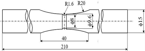
The material used is SCM822H, an alloy steel for mechanical structures. Table 1 shows the chemical composition of the material. The specimen shape (shape factor 𝑎=1.56) is shown in Fig. 1. The gas carburizing quenching tempering specimens (GCT) were carburized at 1,203 K for 4 hours, followed by oil quenching (Q), and tempered at 433 K for 2 hours. Subsequently, middle temperature tempering was conducted at 573 K for 2 hours, followed by DSP under the conditions shown in Table 2.
The combinations of surface modification methods applied to each specimen are shown in Table 3. The base metal specimen (BM) is the GCT specimen, GCT1 is the specimen that done DSP on the BM. GCT2 is the specimen that was tempered at 573 K on the BM and then done DSP. GCT3 is the specimen that done DSP on the BM followed by tempering at 573 K.
2.2 Evaluation method of surface characteristics
Before experiment, the hardness distribution, amount of retained austenite (γR), and residual stress (σr) in the depth direction of the notch area were measured. The hardness measurements were conducted using a Vickers hardness tester with an indentation load of 2.9 kN. γR was obtained from the XRD data using the maximum values of 2𝜃 for each phase.7,8) Residual stresses were measured in the depth direction using the hole drilling method.
2.3 Bending fatigue test method
Bending fatigue tests were conducted using a rotating bending fatigue testing machine of Ono type (Maximum bending moment 15 Nm). The applied stress was calculated by multiplying the nominal stress at the notch section by the shape factor α=1.56. The fatigue limit was defined as the maximum stress amplitude that could withstand for 107 loading cycles.
2.4 Evaluation of harmless crack size
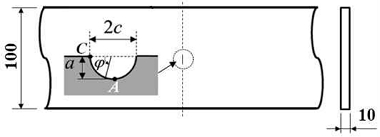
The evaluation specimens are subjected to bending stress with a stress ratio of R=1, as shown in Fig. 2, with a width of W=100 mm and a thickness of t=10 mm. The specimens feature a semi-elliptical surface crack characterized by a crack depth (a) and crack length (2c) with a crack aspect ratio (As=a/c) of 1.0. The crack depth and crack surface are denoted as A and C, respectively.
3. Results and Discussion
3.1 Effect of phase transformation on hardness
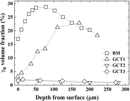
The surface carbon content of the GCT specimen was 0.83 mass%. Fig. 3 shows the distribution of γR content for BM, GCT1, GCT2, and GCT3 specimens. The surface γR content (γRS) of the BM was 17%, which decreased to 3.1% for the GCT1 specimen. This reduction indicates that 81.8% of γRS was transformed into deformation induced martensite due to the DSP. γRS in the GCT2 and GCT3 specimens tempered at 573 K decreased to 1.5% and 1.7%, respectively. This indicates that γR transformed into bainite in the temperature range of 503~543 K. This significant change highlights the effect of surface modification techniques on the microstructural properties of the specimens, ultimately influencing their mechanical behavior.
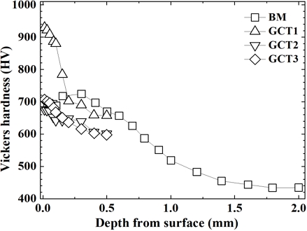
Fig. 4 shows the hardness distribution near the surface of each specimen. The surface hardness (depth 0.01 mm) of the BM, GCT1, GCT2, and GCT3 specimens was 695, 930, 676, and 707 HV, respectively. The hardness of the GCT1 specimen is 235 HV higher than that of the BM. This is attributed to the combined effects of the deformation induced martensite transformation of γR and the conventional work hardening by DSP. When comparing the hardness of the GCT2 and GCT3 specimens tempered at 573 K, the GCT3 specimen showed a hardness that was 31 HV higher.
3.2 Distribution of residual stress
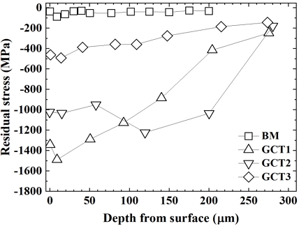
Fig. 5 shows the distribution of residual stress for each specimen. The surface compressive residual stress (σrs) for the BM, GCT1, GCT2, and GCT3 specimens were 36 MPa, 1343 MPa, 1023 MPa, and 462 MPa, respectively. GCT3 showed a low σrs because surface plastic flow remained. The maximum compressive residual stress (σrmax) was determined considering the depth of fatigue cracks at Stage I of high-strength steels and the depth of fatigue cracks of the transition stage from Stage I to Stage II. Thst is, approximately 3 grain sizes (around 60 μm) is a maximum value. σrmax for the GCT1, GCT2, and GCT3 specimens were 1489 MPa, 1034 MPa, and 492 MPa, respectively. The depths for σrmax were 9 μm, 15 μm, and 14 μm, indicating that σrmax were introduced at nearly the surface, within one grain size (about 20 μm). Naturally, considering the temperature rise up to 573 K during operation, the GCT2 specimen, which done DSP after tempering at 573 K, exhibited a σrmax of 542 MPa, which is higher than that of the GCT3 specimen. Therefore, the GCT2 specimen, with its elevated compressive residual stress, is expected to show an improvement in fatigue limit compared to the GCT3 specimen.
3.3 Fatigue limit
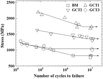
The S-N curves for the GCT1, GCT2, and GCT3 specimens are shown in Fig. 6. The bending fatigue limit for BM was 827 MPa.
However, the bending fatigue limit for the GCT1 specimen, which done after GCT, was significantly higher at 1,732 MPa. Considering the temperature rise to 573 K during operation, the bending fatigue limit for the GCT3 specimen was 1,045 MPa. In comparison, the bending fatigue limit for the GCT2 specimen, which done DSP after tempering at 573 K, was 1,357 MPa. This indicates that the bending fatigue limit of the GCT2 specimen is 30% higher than that of the GCT3 specimen.
Considering the temperature rise during operation, the differences in surface properties between the specimens that were tempered again at 573 K and those that were not were minimal. Therefore, to prevent bending fatigue failure of gears due to unexpected temperature increases during operation, the GCT2 specimen, which done DSP after tempering at 573 K, can be deemed effective.
Table 4 provides a comprehensive summary of the surface properties and fatigue limits obtained from the experiments. This shows surface hardness, maximum residual stress, yield stress, and bending fatigue limit for the various specimens (BM, GCT1, GCT2, and GCT3). The data presented in Table 4 facilitates a clear comparison of how different surface modification techniques and treatments influence the mechanical performance and durability of the specimens, highlighting the effectiveness of the DSP treatment in enhancing both surface characteristics and fatigue resistance.
3.4 Evaluation of harmless crack size (ahml)
Fig. 7(a)~(c) shows the relationship between ΔKTr and ΔKth as a function of crack depth (𝑎) for the GCT1, GCT2, and GCT3 specimens with a crack aspect ratio of As=1.0. ΔKth corresponding to crack length was evaluated using Eq. (1) when a semi-elliptical surface crack in a finite plate is subjected to bending stress with a stress ratio R.9)
| (1) |
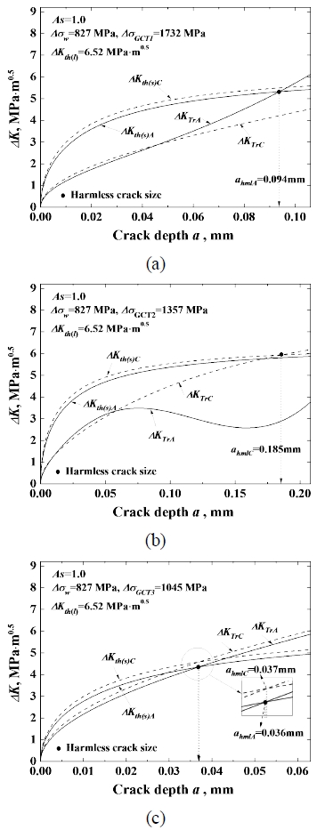
Evaluation of maximum crack size for GCT specimens that can be rendered harmless by DSP. (a) GCT1, (b) GCT2, (c) GCT3
Where Δσw is the fatigue limit of BM at 827 MPa, and ΔKth(l) is the threshold stress intensity factor for long crack, given as 6.52 MPa. 𝑎 is the semi-elliptical crack depth, while β is the shape correction factor from the Newman-Raju equation10) in the crack depth and surface in the case of a finite plate subjected to bending fatigue stress.
ΔKTr is the sum of ΔK calculated using the Newman-Raju equation and Kr obtained from Eq. (2) of the compressive residual stress. The applied stress used in calculating ΔK is the fatigue limit (σw) of each specimen listed in Table 4. Additionally, the evaluation of Kr used the residual stresses shown in Fig. 5 for each specimen.11)
| (2) |
Where G0 ~ G4 are the shape correction coefficients for the stress intensity factor according to API-RP579. a and c represent the depth and surface length of the semi-elliptical crack, respectively. W and t represent the plate width and plate thickness, respectively. σ0 ~ σ4 are coefficients obtained from the residual stress distribution using the fourth-order polynomial.
ahml by DSP is determined by Eq. (3). That is, ahml is determined the smaller crack size in the crack depth and the surface crack. In Fig. 7, all ahml is shown as ● at the intersection points of ΔKth(s) and
| (3) |
Since the hardness of BM before GCT used in this study is 440 HV, a threshold stress intensity factor of 6.52 MPa was applied.12)
(a) In GCT1, the intersection point of ΔKth(s) and ΔKTr was obtained at depth A, and ahml is a crack depth of 0.094 mm. (b) In GCT2, the intersection point was first obtained at surface C, and ahml is a surface crack of 0.185 mm. Meanwhile, (c) In GCT3, the intersection point at depth A (0.036 mm) and surface C (0.037 mm) were nearly identical, resulting in almost no difference in ahml. This means that cracks smaller than ahml can be rendered harmless by DSP.
4. Conclusions
To prevent the reduction on fatigue limit of carburized products due to a sudden temperature rise during operation, specimens were prepared which done DSP after tempering at a middle temperature of 573 K. The surface characteristics and fatigue limits of these specimens and specimens tempered at 573 K after DSP were evaluated. Additionally, the harmless crack size was detemined using the compressive residual stresses by DSP. The obtained results are as follows.
1) GCT1 and GCT3 specimens were compared to surface characteristics. It is presumed that middle temperature tempering thing in which surface characteristics remain largely unaffected, even if the temperature rises during operation. The surface hardness of the GCT3 specimen was 31 to 40 HV lower than that of the GCT2 specimen. This difference is suspected to be due to phase transformations occurring during the DSP and subsequent tempering process at 573 K.
2) The maximum compressive residual stress of the GCT2 specimen was 542 MPa higher than that of the GCT3 specimen. Additionally, the fatigue limit of the GCT2 specimen was improved by 30% compared to the GCT3 specimen.
3) The harmless crack size (ahml) of the GCT1 specimen was a crack depth of 0.094 mm. For the GCT2 specimen, the intersection point was obtained at the surface (C), with a harmless surface crack size of 0.185 mm. In the case of the GCT3 specimen, the intersection point was nearly identical at both depth A (0.036 mm) and surface C (0.037 mm). Based on the fatigue limit of BM, the fatigue limit of the peened material, and compressive residual stress, ahml can be evaluated.
4) It means that cracks smaller than ahml can be rendered harmless by DSP. In other words, cracks with a size equal to or less than ahml will not lead to fatigue failure by DSP, and the material can remain in a safe operational state.
Author contributions
J. K. Lee; Conceptualization, Data curation, Investigation, Methodology, Resources. S. H. Yun; Writing-review & editing.
References
- K. Ando, 2005, “Fatigue fracture process and methods for improving fatigue limit”, Kinzoku, 75(10), 980-983.
-
R. O. Ritchie, 1977, “Influence of microstructure on near- threshold fatigue-crack propagation in ultra-high strength steel”, Metal Science (August/September), 368-381.
[https://doi.org/10.1179/msc.1977.11.8-9.368]

-
O. Unal, E. Maleki, I. Karademir, F. Husem, Y. Efe and T. Das, 2022, “Effects of conventional shot peening, severe shot peening, re-shot peening and precised grinding operations on fatigue performance of AISI 1050 railway axle steel”, International Journal of Fatigue, 155, 106613.
[https://doi.org/10.1016/j.ijfatigue.2021.106613]

-
H. Okada, A. Tange and K. Ando, 2004, “Study on improved fatigue strength for metal bellows made of high strength material SUS631”, Transactions of Japan Society of Spring Engineers, 49, 1-7.
[https://doi.org/10.5346/trbane.2004.1]

-
K. Ando, K. Matsui and H. Ishigami, 2000, “Study on DSP and Fatigue Limit of Gear”, Key Engineering Materials, 183-187, 921-926.
[https://doi.org/10.4028/www.scientific.net/KEM.183-187.921]

-
W. Nakao, M. Koshimune, K. Matsui and K. Ando, 2008, “Influence of phase transformation of retained austenite on fatigue limit”, Transactions of Japan Society of Spring Engineers, 53, 9-12.
[https://doi.org/10.5346/trbane.2008.9]

-
C. Y. Kang, S. H. Kim and G. S. Jeong, 2016, “Effect of Cold Working on the Tensile Strength of Fe-26Mn-4Co-2Al Damping Alloy”, Journal of the Korean Society for Power System Engineering, 20(6), 46-50.
[https://doi.org/10.9726/kspse.2016.20.6.046]

-
C. Y. Kang and M. G. Kwoon, 2014, “Effect of Thermomechanical Treatment on the Mechanical Properties of 316L Stainless Steel”, Journal of the Korean Society for Power System Engineering, 18(3), 100-105.
[https://doi.org/10.9726/kspse.2014.18.3.100]

-
K. Ando, K. W. Nam, M. H. Kim, T. Ishii and K. Takahashi, 2020, “Analysis of peculiar fatigue fracture behavior of shot peened steels focusing on threshold stress intensity factor range”, Transactions of Japan Society of Spring Engineers, 65, 35-41.
[https://doi.org/10.5346/trbane.2020.35]

-
J. C. Newman Jr. and I. S. Raju, 1981, “An Empirical Stress-Intensity Factor Equation for the Surface Crack”, Engineering Fracture Mechanics, 15, 185-192.
[https://doi.org/10.1016/0013-7944(81)90116-8]

- American Petroleum Institute, 2000, “API recommended practice 579 fitness for service”, American Petroleum Institute, C3-C10.
-
M. Nakagawa, K. Takahashi, T. Osada, H. Okada and H. Koike, 2014, “Improvement of Fatigue Limit by Shot Peening for High-strength Steel containing Crack-like Surface Defect (Influence of Surface Crack Aspect Ratio)”, Transactions of Japan Society of Spring Engineers, 59, 13-18.
[https://doi.org/10.5346/trbane.2014.13]


