Fatigue Limit Evaluation for Small Crack in Ni 12% STS316L
Abstract
In this study, the fatigue limit and threshold stress intensity factor of Ni 12% STS316L were obtained. The fatigue limit and threshold stress intensity factors of small cracks were also evaluated. The fatigue limit of crack specimens showed good agreement between experimental and calculated results. Furthermore, the crack size evaluated under the maximum operating pressure (87.5 MPa) of the hydrogen storage tank confirmed the safety of the input/output piping system.
Keywords:
Fatigue Limit, Threshold Stress Intensity Factor, Input/output Piping System, Operating Pressure1. Introduction
Since the American electric vehicle and clean energy company, Tesla, was founded in 2003, the automotive market has transitioned from traditional internal combustion engines to eco-friendly vehicles. In the past decades, research and development based on renewable energy has been actively carried out as a solution to global warming.1-6) Hydrogen fuel cell vehicles are creating a differentiated market from conventional electric vehicles.7,8) Theoretically, as the hydrogen charging capacity of the vehicles is increased, the driving distance can be lengthened. The hydrogen storage tank is made by winding carbon fibers on high-strength plastic composites. Khan et al.9) simulated the temperature rise of the tank wall during hydrogen filling of a carbon fiber reinforced plastic tank. The results were compared with the experimental data of the Japan Automobile Research Institute (JARI). The hydrogen storage tank is about 60% lighter and more than 10 times stronger than the conventional metal fuel tank. The hydrogen storage tank has a working pressure of 70 MPa, a maximum working pressure of 87.5 MPa, and a working temperature of -40 to 85℃.10) Regulators, manifolds, and solenoid valves of hydrogen storage tanks use Ni 12% STS316L to minimize the effects of corrosion and hydrogen embrittlement.11) As these parts are subjected to frequent temperature and pressure fluctuations during operation, the presence of micro cracks can lead to catastrophic failures resulting in human fatalities and and significant economic losses.
The micro crack problem is not established a small-scale nonlinear region assumption, while it is inherently nonlinear problem. Haddad et al.12) proposed an evaluation equation for the crack length dependence of the threshold stress intensity factor (ΔKth) based on the sum of crack length (l) and micro crack length (l0). Subsequently, Tange et al.13) modified Haddad’s equation to develop a more convenient expression. Meanwhile, Ando et al.14-16) introduced a threshold stress intensity factor and fatigue limit evaluation equation for fatigue cracks that incorporates the crack tip process zone, enabling a unified treatment of fracture mode, including brittle fracture, fatigue fracture, hydrogen embrittlement, and stress corrosion cracking. This equation demonstrated accurate prediction of the fatigue limit.
This study aimed to assess the safety of STS316L under the working stress conditions. Initially, the fatigue limit (Δσw) of smooth specimen and the threshold stress intensity factor (ΔKth(l)) of the large crack were determined. Subsequently, the fatigue limit (Δσwc) of a cracked specimen and the threshold stress intensity factor (ΔKth(s)) of the small crack were evaluated. Furthermore, by estimating the crack size based on the maximum working pressure (87.5 MPa) and the fatigue limit reduction ratio of the hydrogen storage tank, and the safety of STS316L was confirmed.
2. Experimental method
2.1 Material
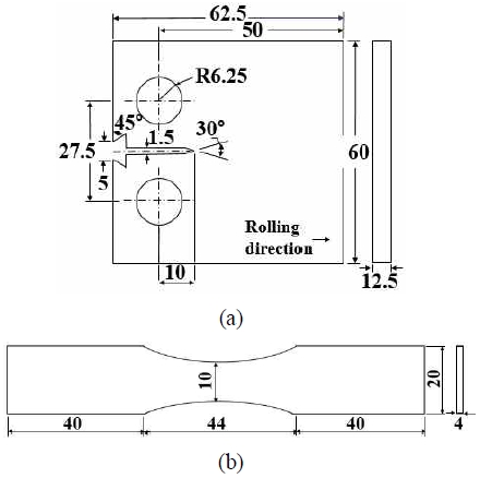
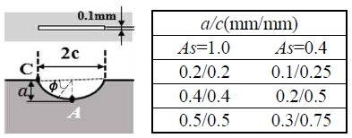
The material used in this study is austenitic stainless steel STS316L for the piping of hydrogen storage tanks. Table 1 shows the chemical compositions of the material, and Table 2 shows the mechanical properties. Fig. 1(a) illustrates a CT specimen with a thickness of 12.5 mm used to determine ΔKth(l), while Fig. 1(b) shows a smooth specimen with dimensions of 10 mm width, 124 mm length, and 4 mm thickness used to obtain Δσw. Fig. 2 shows the dimensions of the semi-elliptical slit introduced into the crack specimen. To accurately evaluate the initiation and growth of a small crack, a very small crack is required. However, making such a small slit using electric discharge machining (EDM) was very difficult. Consequently, the dimensions were decided as shown in Fig. 2. The semi-elliptical slit was subsequently introduced at the center of the smooth specimen through the EDM process. The aspect ratios (As=a/c) of the semi-elliptical slit are 1.0 and 0.4, where, a is the crack depth, and c is a half of the crack length. Depth a is varied as 0.2, 0.4, and 0.5 mm at As=1.0, and 0.1, 0.2, and 0.3 mm at As=0.4.
The aperture width of the slit was approximately 0.1 mm. To eliminate work-hardening after introducing the semi-elliptical slit, it was water-cooled after maintaining for 20 min at 1,050℃ of Ar atmosphere.
2.2 Fatigue test method
The threshold stress intensity factor (ΔKth(l)) of the large crack and the fatigue limit (Δσw) of the smooth specimen were investigated. The fatigue test was conducted at room temperature using a fatigue testing system (nominal dynamic load rating: ±100 kN). The experiment for ΔKth(l) and Δσw was carried out according to fatigue test method of Korean standard (KS B ISO 12108). ΔKth(l) was estimated by the ΔK-decreasing test for long crack, and Δσw was estimated by constant stress amplitudes test. The fatigue tests were performed with a stress ratio R=0.1. All the tests were performed at a frequency of f=20 Hz. The fatigue limit was defined as the maximum stress amplitude at which the specimen could endure 5×10⁶ cycles.
2.3 Evaluation method
This study used Eq. (1), which was proposed by Ando et al.14) This equation describes the dependence of the threshold stress intensity factor range (ΔKth) on crack length when an existing crack in an infinite plate propagates under fatigue stress.
| (1) |
Where a is the crack depth, ΔKth(l) is the threshold stress intensity factor range for the large crack, Δσw is the fatigue limit of the smooth specimen, β is a function of ϕ in Fig. 2 and a shape factor obtained by the Newman–Raju equation.17) In contrast, the fatigue limit (Δσwc) of the cracked specimen can be evaluated using Eq. (2).
| (2) |
Eqs. (1)~(2) are used to determine ΔKth and Δσwc for the deepest part of the crack (point A) in the cracked specimen to which bending stress is applied. To determine these values on the outermost surface (point C), a can be replaced with c in Eqs. (1) and (2).
3. Results and Discussion
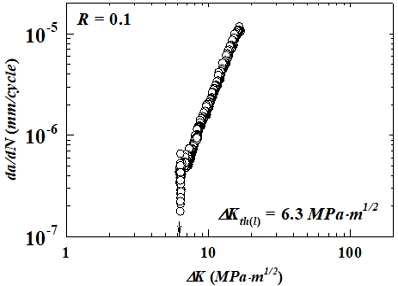
To obtain ΔKth(l), a K-decreasing test was conducted according to the KS standard using three compact tension (CT) specimens. Fig. 3 shows the results obtained from the experiment. ΔKth(l) represents the ∆K value where da/dN approach zero. While typically defined as the ∆K corresponding to 10-8 mm/cycle for most materials, in this study, da/dN converged to zero (0) at 4.1×10⁻⁷ mm/cycle. This ∆K value was determined as the threshold stress intensity factor (ΔKth(l)) for the large crack, equaling 6.3 MPa·m0.5.
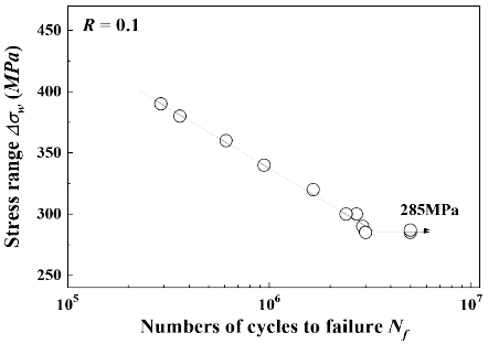
Fig. 4 shows the S–N curve for determining the fatigue limit (Δσw) of the smooth specimen. The arrow symbol (→) indicates specimens that did not fracture after 5×10⁶ cycle. Based on this data, the fatigue limit (Δσw) for STS316L was determined to be 285 MPa.
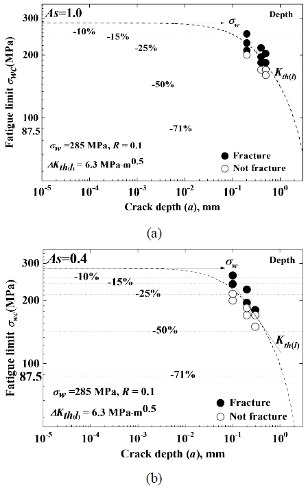
Fig. 5 shows the relationship between fatigue limit (Δσwc) and crack depth for two aspect ratios: is As=1.0 (Fig. 5(a)) and As=0.4 (Fig. 5(b)). Solid circles (●) show fractured specimens, while open circles (○) indicate unfractured ones. The dotted line, representing the calculated fatigue limit curve as a function of crack depth, is obtained from Eq. 2. While the straight line in the figure denotes the fatigue limit (Δσw) of the smooth specimen, it's evident that the fatigue limit decreases with increasing crack depth. The slope of this decrease corresponds to the threshold stress intensity factor of the large crack. Notably, the reduction in fatigue limit is more pronounced for As=0.4. In the small As, the fatigue crack propagates in the depth direction, because the surface crack is large. When the crack depth increases to some extent, the surface crack begins to propagate. The experiment results were in good agreement with the calculation results using Eq. 2. The dotted lines in Figs. 4(a) and 4(b) represent fatigue limit reduction ratios of 10%, 15%, 25%, and 50%. Additionally, a dotted line indicating a 71% fatigue limit reduction, corresponding to the maximum working pressure of the hydrogen storage tank (87.5 MPa), was also shown.
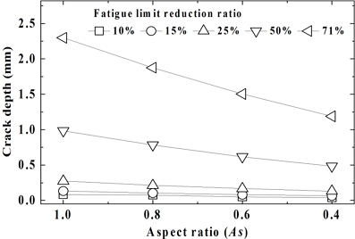
Fig. 6 shows the relationship between crack depth and fatigue limit reduction ratio for various As. Data points for As=1.0 and 0.4 were obtained from Fig. 4, while those for As=0.8 and 0.6 were calculated using Eq. 1. The results indicate that crack depth is influenced by both fatigue limit reduction ratio and As. For a given fatigue limit reduction ratio, crack depth decreases as As decreases. Specifically, the crack depth for As=0.4 is approximately half that of As=1.0. Conversely, at a fixed As, crack depth increases with increasing fatigue limit reduction ratio. It's noteworthy that crack depths for all As remain relatively small up to a 25% fatigue limit reduction ratio. The fatigue limit reduction ratio of 50% was about 12 times of 10%, about 7.4 times of 15%, and about 3.6 times of 25%. That is, the crack lengths for fatigue limit reduction ratio of 50% were 0.983 mm, 0.783 mm, 0.6166 mm, and 0.485 mm for As=1.0, 0.8, 1.6, and 0.46, and As=0.4, respectively. For a 71% fatigue limit reduction ratio, corresponding to the maximum working pressure of 87.5 MPa, crack depths were 2.298 mm, 1.875 mm, 1.504 mm, and 1.188 mm for As=1.0, 0.8, 0.6, and 0.4, respectively. These depths represent 76.6%, 62.5%, 50.1%, and 39.6% of the 3 mm thick material used in this study. At this 71% reduction, calculated crack lengths were 2.298 mm, 2.344 mm, 2.507 mm, and 2.970 mm for As = 1.0, 0.8, 0.6, and 0.4, respectively.
Rummel et al.18) investigated the detection ratio of semi-elliptical fatigue crack. They used ultrasonic nondestructive testing under optimal indoor conditions. Crack with a detection probability of 100% was dimensions of 2c=12 mm and a=4 mm. For a detection probability of 50%, the dimensions were 2c=1.2 mm and a=0.26 mm. The minimum detectable crack size was 0.17 mm in both depth and length. Recently, with the advancement of non-destructive technology, Ochiai et al.19) measured stress corrosion cracks with a depth of 0.4 mm using laser ultrasonic nondestructive testing. Consequently, when employing laser ultrasonic nondestructive testing, cracks that correspond to 50% and 71% of the fatigue limit reduction ratio in this study are 100% detectable, ensuring safety.
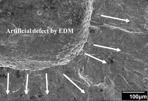
Fig. 7 shows a fatigue fracture surface, with arrows indicating the direction of fatigue crack propagation.
Crack occured at the tip of an artificial defect made by EDM. Numerous ratchet marks are observed at the crack tip, which are caused by the concentration of stress at the artificial defect's tip. These ratchet marks are fatigue indicators, as described by Becker et al.20)
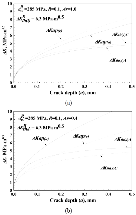
Fig. 8 shows the stress intensity factor (ΔKap) and the threshold stress intensity factor (ΔKth(s)) as functions of crack depth. ΔKap represents the stress intensity factor under applied stress, while ΔKth(s) denotes the threshold stress intensity factor for the small crack. Figs. 8(a) and (b) show the results for aspect ratios As=0.1 and 0.4, respectively, with calculated using Eq. 1. The subscripts A and C denote crack depth and crack length, respectively. The values ΔKap(a) and ΔKap(c) obtained from the Newman–Raju equation correspond to crack depth and crack length, respectively. In Fig. 7(a), where As=0.1 and a=c, there is no significant difference between ΔKap(a) and ΔKap(c) and corresponding ΔKth(s)A and ΔKth(s)C. However, the value of c is slightly larger. This difference was obtained because the equations for ΔKap and ΔKth(s) use 0° for the surface crack and 90° for the depth crack. Both ΔKap and ΔKth(s) increase with crack growth but do not intersect. An increase in ΔKap indicates that the fatigue crack is propagating. As the fatigue crack propagates, ΔKth(s) approaches ΔKth(l). Fig. 8(b) shows that for an aspect ratio As=0.4, the crack depth (a) is larger than the crack length (c). This is because of the larger discrepancy due to the difference angles used for surface and depth cracks (0°for surface and 90°for depth). Consequently, ΔKap(a) is larger than ΔKap(c). This is consistent with the phenomenon that a smaller the As leads to faster propagation of the fatigue crack in the depth direction. In other words, as the crack propagates in depth and approaches the surface crack length, the surface crack length starts to propagate as well. It can be observed that ΔKap(a) increases as As decreases.
4. Conclusions
In this study, the threshold stress intensity factor and fatigue limit of Ni 12% STS316L were determined. The fatigue limit (Δσwc) and the threshold stress intensity factor (ΔKth(s)) of the small crack was evaluated. Additionally, the crack size was assessed at the maximum working pressure of 87.5 MPa, and ensuring the safety of the input/output piping system.
1) The fatigue limit (Δσwc) for crack specimens was calculated by using ΔKth(l) and Δσw. Δσwc decreased as the crack depth increased, with smaller values observed for smaller aspect ratios (As). As the crack grew, ΔKth(s) approached ΔKth(l). The experimentally determined Δσwc showed good agreement with the calculated Δσwc.
2) For As=0.4, the crack depth corresponding to the fatigue limit reduction ratio was approximately half that of As=1.0. The cracks with a 50% reduction ratio were found to be approximately 3.6 times larger than those with a 25% reduction ratio. At the same fatigue limit reduction ratio, cracks with smaller 𝐴𝑠 were evaluated as smaller and safer.
3) The cracks with a fatigue limit reduction ratio of 50% and 71% (at the maximum working pressure of 87.5 MPa) can be detected with 100% accuracy, and the safety of the piping system was ensured.
Author contributions
J. K. Lee; Conceptualization, Data curation, Investigation, Methodology, Resources, Writing-review & editing.
References
-
A. Soleimani, S. Hosseini Dolatabadi, M. Heidari, A. Pinnarelli, B. Mehdizadeh Khorrami, Y. Luo, P. Vizza and G. Brusco, 2024, “Progress in hydrogen fuel cell vehicles and up-and-coming technologies for eco-friendly transportation: an international assessment”, Multiscale and Multidisciplinary Modeling, Experiments and Design, 7, 3153-3172.
[https://doi.org/10.1007/s41939-024-00482-8]

-
M. A. Aminudin, S. K. Kamarudin, B. H. Lim, E. H. Majilan, M. S. Masdar and N. Shaari, 2023, “An overview: Current progress on hydrogen fuel cell vehicles”, International Journal of Hydrogen Energy, 48, 4371-4388.
[https://doi.org/10.1016/j.ijhydene.2022.10.156]

-
S. H. Kim, Y. M. Choi, K. H. Hang, J. H. Shim, I. C. Hang and T. W. Lim, 2011, “The evaluation of fire reliability for the high pressure hydrogen storage system of fuel cell vehicle (1)”, The Korean Hydrogen and New Energy Society, 22, 520-526.
[https://doi.org/10.7316/khnes.2011.22.4.520]

-
T. H. Hyun and V. Arvind, 2014, “Hydrogen storage for fuel cell vehicles”, Current Opinion in Chemical Engineering, 5, 42-48.
[https://doi.org/10.1016/j.coche.2014.04.004]

-
M. W. Davids, M. Lototskyy, M. Malinowski, D. van Schalkwyk, A. Parsons, S. Pasupathi, D. Swanepoel and T. vanNiekerk, 2019, “Metal hydride hydrogen storage tank for light fuel cell vehicle”, International Journal of Hydrogen Energy, 44, 29263-29272.
[https://doi.org/10.1016/j.ijhydene.2019.01.227]

-
J. Y. Yoon and K. H. Choi, 2017, “Status and Policy of Renewable Energy in EU”, Journal of Power System Engineering, 21(3), 5-11.
[https://doi.org/10.9726/kspse.2017.21.3.005]

-
G. Frenette and D. Forthoffer, 2009, “Economic & commercial viability of hydrogen fuel cell vehicles from an automotive manufacturer perspective”, International Journal of Hydrogen Energy, 34, 3578-3588.
[https://doi.org/10.1016/j.ijhydene.2009.02.072]

-
M. Granovskii, I. Dincer and M. A. Rosen, 2006, “Economic and environmental comparison of conventional, hybrid, electric and hydrogen fuel cell vehicles”, Journal of Power Sources, 159, 1186-1193.
[https://doi.org/10.1016/j.jpowsour.2005.11.086]

-
Md. T. I. Khan and M. Monde, 2013, “Characteristics of CFRP hydrogen storage vessel on rising temperature in the filling process”, Procedia Engineering, 56, 719-724.
[https://doi.org/10.1016/j.proeng.2013.03.184]

- Commission Regulation, 2010, “Implementing Regulation (EC) No 79/2009 of the European parliament and of the council on type-approval of hydrogen-powered motor vehicles”, No. 406, Official Journal of the European Union, 1-107. (http://data.europa.eu/eli/reg/2010/406/oj, )
-
K. W. Nam, J. E. Paeng and K. Y. Kim, 2020, “Immersion characteristics of STS316L with degree of different cold rolling”, Journal of Power System Engineering, 24(3), 90-97.
[https://doi.org/10.9726/kspse.2020.24.3.090]

-
M. H. EI Haddad, T. H. Topper and K. N. Smith, 1979, “Prediction of non-propagating cracks”, Engineering Fracture Mechanics, 11, 573-584.
[https://doi.org/10.1016/0013-7944(79)90081-X]

-
A. Tange, T. Akutu and N. Takamura, 1991, “Relation between shot-peening residual stress distribution and fatigue crack propagation life in spring steel”, Transactions of Japan Society for Spring Engineers, 36, 47-53.
[https://doi.org/10.5346/trbane.1991.47]

-
K. Ando, R. Fueki, K. W. Nam, K. Matsui and K. Takahashi, 2019, “A study on the unification of the threshold stress intensity factor for micro crack growth”, Transactions of Japan Society for Spring Engineers, 64, 39-44.
[https://doi.org/10.5346/trbane.2019.39]

-
K. Ando, K. W. Nam, M. H. Kim, T. Ishii and K. Takahashi, 2020, “Analysis of peculiar fatigue fracture behavior of shot peened steels focusing on threshold stress intensity factor range”, Transactions of Japan Society for Spring Engineers, 65, 35-41.
[https://doi.org/10.5346/trbane.2020.35]

-
K. Ando, M. H. Kim and K. W. Nam, 2020, “Analysis on Peculiar Fatigue Fracture Behavior of Shot Peened Metal using New Threshold Stress Intensity Range Equation”, Fatigue & Fracture of Engineering Materials & Structures, 44, 306-316.
[https://doi.org/10.1111/ffe.13356]

-
J. C. Newman Jr. and I. S. Raju, 1981, “An empirical stress-intensity factor equation for the surface crack”, Engineering Fracture Mechanics, 15, 185-192.
[https://doi.org/10.1016/0013-7944(81)90116-8]

- W. D. Rummel, P. H. Todd Jr, S. A. Frecska and R. A. Rathke, 1974, “The detection of fatigue cracks by nondestructive testing methods”, NASA Technical Report, NASA-CR-2369.
-
M. Ochiai, T. Miura, S. Yamamoto, 2008, “Lase-ultrasonic testing and its applications to nuclear reactor internals”, AIP Conference Proceedings, 975, 231-238.
[https://doi.org/10.1063/1.2902663]

-
W. T. Becker and J. Shipley, 2002, “Failure Analysis and Prevention - Fatigue Failures”, ASM International, 11, 700-727.
[https://doi.org/10.31399/asm.hb.v11.a0003544]


