PHC 파일용 PC 강봉의 열처리에 따른 미세구조 및 기계적 특성
 ; Bu-An Kim**
 ; Hyong-June Kim***
 ; Jae-Hak Lim****
 ; Sang-Hoon Noh**
 ; Chang-Kwon Moon**, †
Abstract
For prestressing concrete (PC) steel bar, high-strength steel bar with spiral groove is used by deform drawing and heat treatment of medium carbon steel, 30MnSi. Since the ø8.8 mm PC steel bar has to be subjected to a different tempering temperature from the existing ø9.2 mm PC bar, the microstructure after tempering through the induction heat treatment method was comparatively analyzed and the tensile stress-strain curves for each heat treatment condition were investigated. The experiment was conducted by controlling the heat treatment temperature by adjusting the current input value. The change of the linear speed compared to the current value has a great influence on the mechanical properties of the product, and the tempered martensite structure is observed in the specimen to which the current value of 98 A and the line speed of 48 m/min is applied, and the tensile strength is 1,455 N/mm2 satisfied.
Keywords:
Prestressing concrete (PC) steel bar, Heat treatment, 30MnSi, Induction heating, Tensile stress1. 서 론
국내에서는 1990년대 초반 건축물의 고층화 및 대형화, 연약지반 시공 증가 등에 따라 PHC 파일(Pretensioned spun high strength concrete pile)의 제조기술을 도입하여, 현재 단일 파일로는 세계 최대 규모의 시공량 수준을 보인다. 특히, 아파트용 콘크리트 기초의 90% 이상이 PHC 파일을 사용하고 있다.1)
일본의 경우, 지진 발생 시 PHC 파일의 취성 전단파괴로 인하여 건축물이 철거되는 사례가 다수 보고되고 있기에, PHC 파일의 취성적 전단파괴를 방지하고 지진 안정성을 확보하기 위하여 PHC 파일의 뼈대 역할을 하는 PC 강봉에 대한 연구가 활발히 이루어지고 있다.2-4) PC 강봉은 중탄소강인 30MnSi를 이형 인발 가공과 열처리로 나선 홈이 있는 고강도의 철강 봉을 사용한다. 고강도의 PHC 파일에 관한 연구2)가 진행됨에 따라, 뼈대인 PC 강봉의 수가 증가한 PHC 파일에 적용할 수 있는 ø8.8 mm PC 강봉에 대한 수요 발생으로 ø9.2 mm PC 강봉과 동등 수준의 인장하중이 보장되는 ø8.8 mm PC 강봉의 열처리 조건 확보가 필요하게 되었다. 일반적인 PC 강봉의 열처리는 진직성 확보를 위하여 인장하중 대비 10~20%의 인장력이 유지되는 유도 가열 방식의 열처리 설비에서 진행되며, ø8.8mm PC 강봉은 ø9.2 mm PC 강봉의 요구 특성인 1420MPa 이상의 인장 강도와 연신율 10% 이상 및 240-440 HV10의 경도가 보장되어야 한다. PC 강봉은 담금질과 뜨임 열처리로 제조된다. 미세조직은 기계적 성질에 큰 영향을 미치게 되며, PC 강봉의 경우, 미세조직은 마지막 열처리인 뜨임 온도에 따라 결정된다.5-9)
본 연구에서는 태광금속(주)의 인발 가공기 및 유도 가열 열처리기를 이용하여 KS B 0801의 2호 시험편을 제작하여 여러 가지 조건의 열처리 조건으로 변형율 속도 2.5×10⁻⁴ s-1를 적용한 인장시험 후 최적의 열처리 조건을 도출하였다.
2. 재 료
본 연구에서 시험편 제작을 위하여 사용된 철강재료는 ø9.2mm PC 강봉과 동일한 재료인 한국의 POSCO에서 제조된 30MnSi의 중탄소강을 사용하였다. ø10mm의 30MnSi 선재에서 3개의 시험편을 채취하여 습식분석법을 이용하여 화학 성분 분석을 실시하였으며, 그 결과는 Table 1에 나타내었다.
인장시험을 통하여 시험편의 기계적 특성을 분석하였으며 그 결과는 Table 2에 나타내었다.
3. 실험 방법
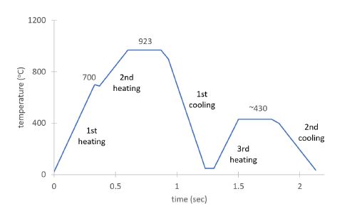
시험편을 제작한 태광금속(주)는 ø9.2 mm PC 강봉을 생산하고 있으며, 사용한 유도 가열 방식의 열처리기의 사양 및 ø9.2 mm PC 강봉 생산에 사용된 전류 크기 및 온도는 Table 3에 나타내었다. ø9.2 mm PC 강봉은 원소재인 선재(steel wire)를 이형 인발 가공 후, Ac3 변태점 이상의 온도로 가열 후, 담금질과 뜨임으로 1,400 MPa의 인장강도를 가지게 된다. 자세한 열처리 선도는 Fig. 1에 나타내었다.
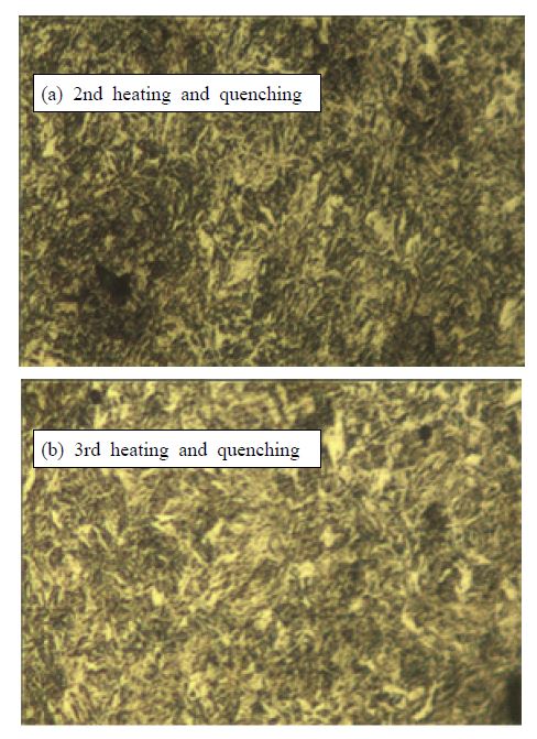
ø9.2 mm PC 강봉의 미세구조를 광학현미경으로 관찰한 결과, 2차 가열 후에는 마르텐사이트 조직이 나타났으며 3차 가열 후에는 마르텐사이트 조직과 유사한 조직이 관찰되었으나 템퍼드 마르텐사이트 조직으로 판단되었다. 2차 및 3차 가열 후의 미세조직 관찰 결과를 Fig. 2에 나타내었다. 전류 입력값을 조정하여 열처리 온도를 제어하고 있으므로, 본 실험에서는 제품의 기계적 특성에 영향을 줄 수 있는 3차 가열(G3) 전류값 및 이송속도(선속)를 변수로 설정하여 실험을 진행하였다. 실험에 사용된 유도가열 조건은 Table 4에 나타내었다. 1차 가열(G1) 및 2차 가열(G2)을 위한 전류값은 ø9.2 mm PC 강봉 생산에 사용되는 전류값을 사용하였으며, 감소된 단위 길이당 질량에 따른 생산성 저하가 발생하지 않도록 최저 선속(46 m/min)을 이송속도(선속) 변수값으로 사용하였다.
4. 결과 및 고찰
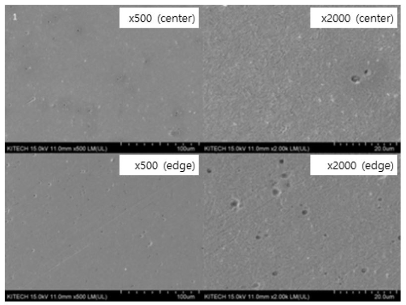
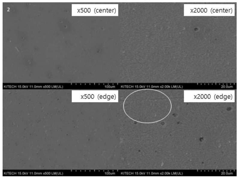
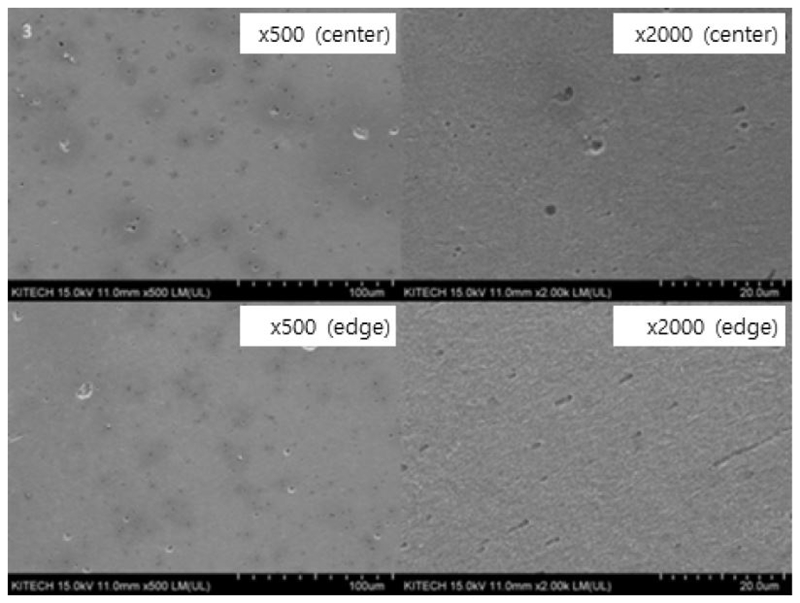
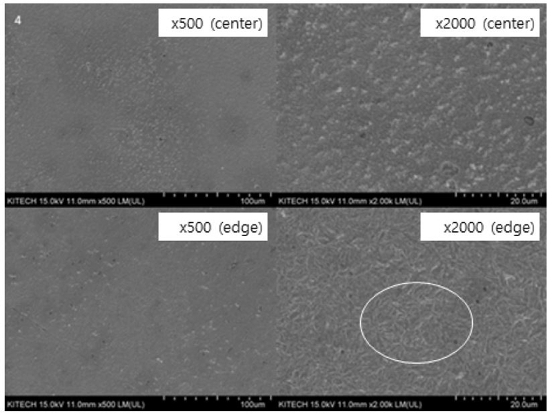
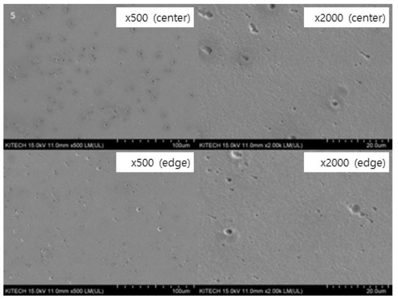
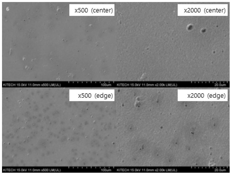
Fig. 3~8은 각 시편을 오스테나이트화 온도에서 급냉 후, 시험 조건별 온도에서 뜨임 및 냉각한 시편에 대한 미세조직을 전자현미경으로 관찰한 결과이다. Fig. 3 및 Fig. 4는 G3 입력 전류 98 A에서, Fig. 5 및 Fig. 6은 G3 입력전류 97 A에서, Fig. 7 및 Fig. 8은 G3 입력전류 96 A에서 각각 이송속도를 변화시키며 뜨임 열처리한 미세조직이다. 시편 2(Fig. 4)와 시편 4(Fig. 6)의 미세구조는 ø9.2 mm PC 강봉의 템퍼드 마르텐사이트 조직과 유사한 조직이 관찰되었지만, 시편 1(Fig. 3), 시편 3(Fig. 5), 시편 5(Fig. 7)에서는 마르텐사이트 조직이 관찰되지 않았으며, 이는 빠른 이송속도로 인하여 충분한 열처리가 이루어지지 않은 것으로 판단된다.
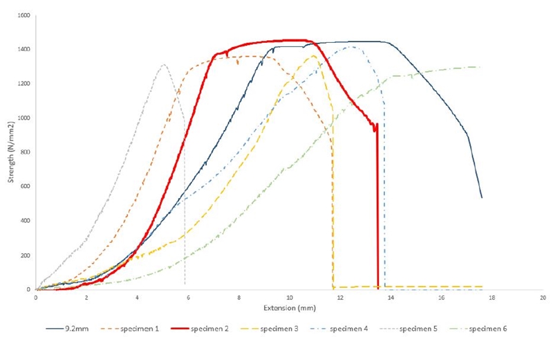
Fig. 9는 G3 전류 및 이송속도 변화에 따른 뜨임 열처리된 30MnSi ø8.8 mm PC 강봉의 인장응력-변형율 곡선을 나타내었다. PC 강봉에 인성을 부여하기 위하여 400oC 이상의 온도에서 뜨임 열처리를 하였으며, 연속 제조 설비로 인하여 이송속도 변화를 통한 미세한 변화를 부여할 수 있었다. PC 강봉의 재료인 30MnSi의 경우, 뜨임 열처리 온도 427oC에서도 1 GPa급 이상의 인장강도를 확보할 수 있음을 알 수 있다. 그러나 시편 3과 시편 5는 낮은 뜨임 온도에 의하여 불충분한 뜨임 열처리가 이루어져 낮은 연신율(약 5%)을 가지는 것으로 나타났다. 뜨임 온도가 430oC 이상인 시편 2 및 4는 인장강도 1,400 MPa 이상을 나타내었지만 ø9.2 mm PC 강봉과 유사한 미세구조를 가지는 시편 2의 인장강도가 가장 큰 1,455 MPa를 나타내었다. 또한 유도 가열 열처리기의 짧은 온도 유지 시간 및 빠른 이송 속도로 인하여 시편 2에서는 마르텐사이트 조직이 시편 4 대비 많이 잔존하는 것으로 판단되며, 이에 따라 연신율 하락이 발생한 것으로 판단된다.
5. 결 론
중탄소강인 30MnSi를 사용하여 생산되는 ø8.8 mm PC 강봉은 기존의 ø9.2 mm PC 강봉과 다른 뜨임 온도가 적용되어야 하므로 유도 가열 열처리 방식을 통하여 뜨임 후의 미세조직들을 비교 분석하고, 열처리 조건별 인장응력-변형율 곡선을 조사하여 다음과 같은 결론을 얻었다.
1) G3 전류값 및 선속 변경 시험 결과, 전류값 대비 선속도 변경이 제품의 기계적인 특성에 많은 영향을 끼치며, 최적값은 G3 전류 98 A 및 선속 48 m/min인 것으로 나타내었다.
2) 최적값이 적용된 시편 2의 경우, 기존 제품(ø9.2 mm PC 강봉)과 유사한 미세조직(템퍼드 마르텐사이트)이 관찰되며, 인장강도는 1,455 N/mm2으로 제품의 허용값(1,420 N/mm2)을 충족하는 결과를 보였다.
Acknowledgments
이 논문은 부경대학교 자율창의학술연구비(2021년)에 의하여 연구되었음.
Author contributions
C. S. Oh; Conceptualization. C. K. Moon & H. J. Kim & N. S. Hoon; Data curation. C. K. Moon & H. Kim & N. S. Hoon; Formal analysis. J. H. Lim; Funding acquisition. C. K. Moon; Project adminstration. C. K. Moon; Supervision. C. S. Oh; Validation. H. J. Kim; Visualization. C. S. Oh; Writing-original draft. B. A. Kim; Writing-review & editing.
References
-
M. H. Kim and Y. G. Choi, 2018, "Study on the Applicability of Dynamic Pile Load Test to Check Integrity during Installation of Extension Plate Attached PHC Piles and Bolts Spliced PHC Piles and the Correct Proof Test of the Transformed-installation PHC Piles", Journal of the Korean Geotechnical Society, Vol. 34, No. 12, pp. 115-131.
[https://doi.org/10.7843/kgs.2018.34.12.115]

- C. H. Park and S. G. Kang, 2001, "Failure Investigation of Shear Stressed Bar in PC Box Bridge", Proceedings of the Korea Institute for Structural Maintenance and Inspection, Vol. 5, No. 2, pp. 91-96.
- T. H. Kim, 2011, "An effective connection method for steel girder and PC column by thread bars", Proceeding of the Architectural Institute of Korea, Vol. 31, No. 2, pp. 351-352.
- J. H. Byun, Y. B. Kim and H. J. Jeong, 1999, "LMI Based H∞ Active Vibration Control of a Structure with Output Feedback : Experiment Results", Journal of Power System Engineering, Vol. 3, No. 3, pp. 83-90.
- G. Z. XIAO, H. S. DI and X. J. Jia, 2007, "Effect of Heat Treatment on Microstructure and Mechanical Properties of 30MnSi Pre-Stressed Concrete Steel", Iron & Steel, Vol. 42, No. 4, p. 4.
- T. Murai, 2011, "Direct Heat Treatment Technique for High-Strength, Large-Diameter PC Steel Bars with Pearlite Microstructure", SEI Technical Review, No. 73, pp. 31-34.
- D. J. Yoon, E. Z. Kim, S. T. Ahn and Y. H. Yoon, 2009, "Development of Pre-heat-treated High Strength CHQ Wires and Forming Technology for them". Proceedings of the Korean Society for Technology of Plasticity Conference, pp. 35-36.
-
J. B. Lee, N. Kang, J. T. Park, S. T. Ahn, Y. D. Park, I. D. Choi, D. G. Nam and K. M. Cho, 2010, "Tensile Properties of Energy Saving Wire (ESW) with respect to Temperatures of High Frequency Induction Heat Treatment", Korean Journal of Metal and Materials, Vol. 48, No. 11, pp. 974-980.
[https://doi.org/10.3365/KJMM.2010.48.11.974]

- G. Y. Kim, B. H. Jung and Y. S. Ahn, 2001, "The Effect of Heat Treatment on the Microstructural Evolution and Mechanical Properties of Co-base Materials", Journal of Power System Engineering, Vol. 5, No. 2, pp. 63-70.

