Theoretical Investigation and Modelling of Microjet in Cavitation
Abstract
Microjet from the cavitation causes damages to surface and a theoretical investigation may pave a way to engineering innovations resulting in less or no cavitation effects at all. This paper concentrates on the physics of microjet formation. Microjet impacts mostly on the surface because of the low or zero pressure. In addition to this, we have proposed a model which may possibly cover the fluid physics such as the Rayleigh Plesset Equation. We have found that only smooth surfaced materials can generate the micro bubbles for a longer period under insonation. An attempt is made to derive a theoretical model for the physical phenomena. Using the theoretical modeling, we can predict the cavitation effect. This study also shows the predominance of pressure difference in the Cavitation number.
Keywords:
Cavitation, Microjets, Modeling1. Introduction
Cavitation results in noise, vibration and structural damage.1) Microjet plays a predominant role in creating damage and always directs out to the near solid wall boundary.2) A detailed study of the cavitation and microjet along with the existing experiment and numerical results is presented in this work. The aim of this study is not to provide a solution for cavitation effect but to investigate on microjet formation. This investigation may give a solid finding about microjets which can be used to solve the cavitation problem.
When high pressure water jet is in contact with surface, the bubble clouds is generated. The bubble collapse and affect the surface which is more like peening process. The process is called Water Cavitation Peening (WCP) that improves the fatigue life of the components.3) When the jet impinges the solid boundary, primary jet ring vortex and secondary vortex forms.4) The viscosity of liquid plays an important role in vorticity and turbulence.1) This vortex formations may be applicable even to microjets.
Cavitation inception study is significant in the research to control cavitation. Road et al. reviewed the mechanics of Cavitation Inception. It is based on the Turbulent flow structures and controlling the boundary layer flow structures will control the cavitation.
Presence of asymmetry like nearby wall, gravity, etc. can cause the microjet formation and directs towards the wall. Microjets is dependent on the initial position of bubble from the solid wall and shape. Tomita and Shima documented the formation of two toroidal vortex bubbles. Shock waves and microjets are formed from cavitation. The stress resulted from these two factors, after a certain repetition, will cause the fatigue failure and detachment or flake off materials from the surface. Microjets creates individual pits and cluster of small bubbles that form cavitation. The effects of small bubble cluster are 2 to 3 times of the microjet.2)
When the bubble is near the wall, the asymmetry causes the bubble to collapse generating the vortex in the span wise direction.2) The author conjectures that the microjet is formed because of reentrants generated from bubble collapse in all the cases. In most of the papers, it is mentioned as a reentrant jet created because of the bubble’s interaction with solid wall. But in Suslick et al.,9) the microjet formation images shows that the microjet may be swirl vortex generated from the bubble collapse rather than the high-speed jet impacting on the surface. These Jets can generate vortexes which can create cluster of micro bubbles.10)
For theoretical modelling, literature review about vortex and related function is considered as a necessity. In most of the problem, angular velocity is replaced by vorticity for simplification. Flow over a vortex flow is explained in detail using stream functions with certain assumptions. When the vortex is combined with the uniform stream flow, the stream function of vortex flow can give the velocities.2) Though the theoretical modelling can be written using the velocities derived from the stream functions,10) the methodology of B. H. Bang et al.6) is adopted because the problem under consideration has a similar profile and conditions. We adopted the velocity profile of the microjet to derive the governing pressure equation. From the literature review, it is found that the micro jet is a high re-entrant jet or the Microjet formation. Following the velocity profile has an added advantage i.e., the velocity profile will be same for microjet irrespective of the formation reasons. The radius of water bubble decides the film thickness, when the time increases the film thickness decrease.
2. Experimental setup and method
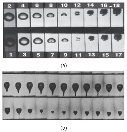
Fig. 2.a shows the microjet from the bubble creating a bubble cloud. Image shows the reentrant jet when the bubble burst. The direction of the reentrant jet gives the location of nearby boundary. It is fascinating that the jet is always directed towards the wall. The reason may be because the boundary has low or zero pressure. Fig. 2.b shows the microjet formation during the cavitation which is resembling a swirling vortex. Note that the impacted jet shape from the studies are same for both the cases.
2.1 Theoretical modelling for the microjet impact
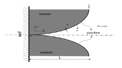
Consider the microjet in contact with the nearby solid wall as shown in Fig. 2. Let L be a characteristic longitudinal scale. Take h as the film thickness between the microjet and water. Origin is marked as the O and distance y is calculated inward from the imaginary boundary of the microjet, as shown in Fig. 2, which is a function of A and B. The constants A and B varies with axial location x and time t. Microjet profile is the function R(x) which is dependent on the x. Pressure of void Pvoid acting on the wall is also a function of x, and t.
B. H. Bang et al.6) derived a theoretical modelling for a swirling flow. The problem is almost same to the description in this paper. Hence adopting the theoretical model from reference6) maybe the apt choice. Consider the longitudinal velocity vs and swirling velocity vɵ profiles for the Microjet as follows :
| (1) |
| (2) |
Substituting equation (1) Substituting equation (3) Substituting equation υs
| (3) |
| (4) |
equation (4) is the continuity equation, where λ is the stretching ratio.
The axisymmetric continuity equation is
| (5) |
| (6) |
Consider,
then the radial velocity component υr
| (7) |
| (8) |
where is the density of the liquid.
| (9) |
equation (9) is the quasi 1D approximation.
| (10) |
equation (10) give the value of pressure, where σ is the surface tension.
Substituting equation (2), the average pressure can be written as
| (11) |
Note that the stress acting on solid wall depends on the area of contact of microjet, distance from a bubble burst and pressure of the gas. Area of contact of microjet with the solid wall is a function of t. The temperature from cavitation is considerably high.6) It can create the temperature stress. Pressure induced because of the temperature is noted as. Cavitation number depends on the local pressure pα, vapor pressure pV, and dynamic pressure qα. The Cavitation number, considering the phase as single-phase flow, can be given by equation (12)
| (12) |
Dynamic pressure , where C is the constant and V is the local velocity. If the local pressure is influenced by the average pressure calculated from equation (11), then the cavitation inception number can be written as in equation (13).
| (13) |
2.2. Numerical Models
Lagrangian bubble based model and large eddy simulation (LES) were used to predict the cavitation flow accurately.11) The model derived for the cavitation dynamics study from Ref. 12 is given below.
| (14) |
where is the vapor fraction, u and v are the velocities in respective x and y axis, the nuclei concentration, and R is the radius of the bubble. It is notable that the Rayleigh relation is chosen for the inertia-controlled bubble growth. Athavale et al. work mentioned that the following governing equation is suited for the simulation of cavitation induced by rotatory components.
| (15) |
Where f is the vapor mass fraction, is the velocity vector, is the effective exchange coefficient, and are the vapor generation and condensation rate terms. Though these models predict the cavitation in the flow with hydrofoil, the effect of microjet is not considered. In our study, we have provided the relation which can be used to include the impact created by the microjet.
Some of the cavitation model in the Fluent, Ansys are Singhal et al., Zwart-Gerber-Belamri, and Schnerr and Sauer model. Singhal et al. model for the non-condensable gases and for the cavitating flow, a constant value of factor proves to be effective for the numerical analysis. Zwart- Gerber-Belamri model assumed that the system has bubble of equal diameter and the bubble density number, and mass change rate were used to derive the relation for interphase mass transfer. Singhal et al., and Schnerr and Sauer model used similar approach to provide the equation for mass transfer between liquid and vapor.15)
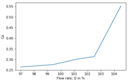
Berchiche et al. showed that bubble model is apt for their study in erosion of the material because of cavitation. Fig. 3 is drawn with the Data from the Dular et al. work on the Cavitation number and flow rate at various operating condition of the rotary component. Lv et al. work proves that the cavitation can be used for manufacturing materials. The abrasives in the fluid flow affects the surface damaged by cavitation.
3. Experimental results and discussion
Fig. 3 shows that the increase in flow rate increases the cavitation number. Changes in pressure near the boundary will change the boiling temperature of the water. Any method reducing this effect can lessen the effect of cavitation. Though the equation (13) is not validated, it can give an approximate Cavitation number. The pressure and density ratio seem to be an important factor which determines the cavitation effect. It is noted that surface tension and thickness of the bubble film also affects the cavitation inception number.
3.1 Proposed Cavitation Model
Since the model used for the cavitation study is complicated, we have proposed a simple governing equation to cover the physics in cavitating flow.
3.2 Equation for bubble motion prediction
Bubble motion equation from Gnanaskandan et al.,
| (16) |
The above equation resembles the Navier Stoke’s equation. Observation shows that the motion of bubble depends only on the excess pressure. Hence, we use the Navier’s Stokes equation for the bubble motion prediction. It is notable that the modified version of Navier Stokes equation can simulate the multiphase flow.19-24) Ibrehem et al. used the artificial neural network to predict the bubble size in bubble column. They have concluded that the work from Akhtar et al., is one of the effective predicts of bubble size for their problem under study. Akhtar et al. researched VOF methods applicability to predict the bubble shape and its motion.
Navier Stokes 2D Momentum equation is given below,
| (17) |
| (18) |
The pressure gradient term is the excess pressure which changes with respect to the axis. u and v are the velocities of the bubble in the respective direction. If we consider the roughness of the surface which results in the loss of the head. The term in equation (17) and (18) can be used to include the head loss term due to friction. equation (19) and (20) is the Darcy`s equation for the head loss. The value of the density is considered as a variable to include the Volume of Fluid (VOF).
| (19) |
| (20) |
4. Conclusions
From the theoretical investigation, it is found that the microjets is formed because of reentrant jet. Literature review shows good evidence of the same. Generation of bubble clouds from the microjet increases the effect of cavitation on the surface. The theoretical modelling for the cavitation is successfully derived from the velocity profile of Microjet. This can be used to calculate the factors influencing the cavitation. Microjet impacts mostly on the surface because of the low or zero pressure. In addition to this, we have proposed a model which may possibly cover the fluid physics like the Rayleigh Plesset Equation. It is noted that the Cavitation number does not rise directly proportional to the flow rate from the study.
When the flow rate rises above 100%, the variation of cavitation number is not linear. Cavitation number from the reference showed that maximum erosion takes place with increase in flow rate. We provide the relation for flow rate and cavitation. Note that the curve fitting with the relation showed a strong dominance of pressure variation. Vortex formation can result in cavitation too, the useful study techniques were presented in.23,24) With the help of these study techniques, we can observe and experimental analysis the Cavitation number.
We are currently working on the cavitation effect on rough and smooth surfaced materials under insonation. We predicted that, over a period of insonation, the damage on smooth surfaced materials is high because it can generate micro bubbles, and cavity formation on rough surface can generate more macro bubbles than micro. We found that only smooth surfaced materials can generate the micro bubbles for a longer period under insonation. Detailed explanation will be presented in the new article with relevant experimental and or theoretical results.
Author contributions
Vijayakumar Mathaiyan; Writing-original draft, Writing-review & editing, Formal analysis, Data curation, Software, Visualization. Dong-Won Jung; Supervision, Conceptualization, Investigation, Methodology, Resources.
References
-
R. E. A. Arndt and A. T. Ippen, 1968, "Rough Surface Effects on Cavitation Inception", Journal of Basic Engineering, Vol. 90, No. 2, pp. 249-261.
[https://doi.org/10.1115/1.3605086]

- C. E. Brennen, 1995, "Cavitation and Bubble dynamics", Oxford University Press.
-
B. Han and D. Y. Ju, 2009, "Compressive Residual Stress Induced by Water Cavitation Peening: A finite Element Analysis", Materials and Design, Vol. 30, No. 8, pp. 3325-3332.
[https://doi.org/10.1016/j.matdes.2008.11.029]

-
J. Long and T. H. New, 2016, "Vortex Dynamics and Wall Shear Stress Behavior Associated with an Elliptic Jet Impinging upon a Flat Plate", Experimental Fluids, Vol. 57, No. 7, pp. 1-18.
[https://doi.org/10.1007/s00348-016-2206-9]

-
E. P. Road, 1991, "Review – Mechanisms of Cavitation Inception", Journals of Fluid Engineering, Vol. 113, No. 2, pp. 163-175.
[https://doi.org/10.1115/1.2909476]

-
B. H. Bang et al., 2019, "Theoretical model for swirling thin films flow inside nozzles with converging-diverging shapes", Applied Mathematical Modelling, Vol. 76, pp. 607-616.
[https://doi.org/10.1016/j.apm.2019.06.025]

-
J. A. Joy, V. Mathaiyan, M. Sajjad and D. W. Jung, 2019, "Numerical Studies on Cavitation and Surface Roughness", Key Engineering Materials, Vol. 793, pp. 79-84.
[https://doi.org/10.4028/www.scientific.net/kem.793.79]

- V. Mathaiyan et al., 2018, "Study on Acoustic Pressure Fluctuations in Solid Rocket Motor and its Effect on Thick Wall", ARSSS Conference Proceedings, pp. 57-60.
-
K. S. Suslick, 1990, "Sonochemistry", Science, Vol. 247, No. 4949, pp. 1439-1445.
[https://doi.org/10.1126/science.247.4949.1439]

- F. M. White, 2018, "Fluid Mechanics", Mc Graw Hills Education.
-
P. Zamankhan, 2015, "Simulation of Cavitation Water Flows", Mathematical Problems in Engineering, pp. 1-6.
[https://doi.org/10.1155/2015/872573]

-
J. Sauer and G. H. Schnerr, 2011, "Development of a New Cavitation Model Based on Bubble Dynamics", Journal of Applied Mathematics and Mechanics, Wiley Online Library, Vol. 81, No. 3, pp. 561-562.
[https://doi.org/10.1002/zamm.20010811559]

-
M. M. Athavale, H.Y. Li, Y. Jiang and A. K. Singhal, 2002, "Application of the Cavitation Model to Pumps and Inducers, International Journal of Rotating Machinery", Taylor and Francis Publication, Vol. 8, No. 1, pp. 45-56.
[https://doi.org/10.1155/S1023621X02000052]

-
N. Berchiche, J. P. Franc and J. M. Michel 2002, "A Cavitation Erosion Model for Ductile Materials", Journal of Fluid Mechanics Engineering, ASME, pp. 601-606.
[https://doi.org/10.1115/1.1486474]

- Fluent, 2009, Cavitation Model, Ansys.
-
M. Dular, B. Stoffel and B. ŠirokMatevz, 2006, "Development of a Cavitation Erosion Model", Wear, No. 5-6, pp. 642-655.
[https://doi.org/10.1016/j.wear.2006.01.020]

-
Z. Lv, R. Hou, Z. Zhang and Z. Fan 2020, "Effect of Ultrasonic Vibration on Cavitation Erosion of Aluminium Oxide in Fluid Jet Machining", The International Journal of Advanced Manufacturing Technology, Vol. 111, pp. 2911-2918.
[https://doi.org/10.1007/s00170-020-06275-w]

-
A. Gnanaskandan, C. T. Hsiao and C. Chahine, 2019, "Modeling of Microbubble-Enhanced High-Intensity Focused Ultrasound", Ultrasound in Med. & Biol., Vol. 45, No. 7, pp. 1743-1761.
[https://doi.org/10.1016/j.ultrasmedbio.2019.02.022]

-
X. D. Shi, M. P. Brenner1 and S. R. Nagel1, 1994, "A Cascade of Structure in a Drop Falling from a Faucet", Science, Vol. 265, pp. 219-222.
[https://doi.org/10.1126/science.265.5169.219]

-
A. S. Ibrehem and M. A. Hussain, 2009, "Prediction of Bubble Size Columns using Artificial Neural Network", Journal of Applied Sciences, Vol. 9, No. 17, pp. 3196-3198.
[https://doi.org/10.3923/jas.2009.3196.3198]

-
A. Akhtar, V. Pareek and M. Tade, 2007, "CFD Simulations for Continuous Flow of Bubbles Through Gas-Liquid Columns: Application of VOF Method", Chemical Product and Process Modeling, Vol. 2, pp. 1-21.
[https://doi.org/10.2202/1934-2659.1011]

-
I. Y. Park, J. S. Kim and D. S. Bae, 2019, "Three-Dimensional Numerical Study on the Mixed Convection in Inclined Rectangular Channels", Journal of the Korean Society for Power System Engineering, Vol. 23, No. 2, pp. 20-26.
[https://doi.org/10.9726/kspse.2019.23.2.020]

-
I. Y. Park, J. S. Kim and D. S. Bae, 2020, "Experimental Study on Vortex Flow in a Rectangular Channel (2)", Journal of the Korean Society of Power System Engineering, Vol. 24, pp. 23-30.
[https://doi.org/10.9726/kspse.2020.24.1.023]

-
L. R. Piao, J. S. Kim and D. S. Bae, 2018, "Experimental Study on Vortex Flow in a Rectangular Channel (1)", Journal of the Korean Society of Power System Engineering, Vol. 22, pp. 37-44.
[https://doi.org/10.9726/kspse.2018.22.2.037]


