윙바디와 냉동탑 특장차용 사이드게이트의 단조 힌지의 특성
Abstract
Wing body and refrigerated van special vehicles incorporate hinges on the sidegate, which in the past has increased the overall width of the vehicle due to the appearance of casting hinge protruding. Under the current road traffic law, the width of the vehicle cannot exceed 2,500 mm except for the side mirrors. Such protruding hinges will result in a width of more than 2,500 mm, which will reduce the width of the interior space reducing the loading efficiency. In addition, the pin inserted into the hole of the hinge threatens the safety accident of the special vehicle due to corrosion and crack. This study is to investigate the characteristics of forged hinges of sidegate for special vehicles to improve high efficiency and corrosion resistance. Although the yield strength of the developed the forging hinge was reduced compared to the casting hinge, the tensile strength increased by about 1.3% and the elongation rate increased by 54%. The maximum stress of the forging hinge was 325 MPa, and it was not destroyed at the fatigue limit of 106 cycles of 250 MPa, which is the target of development. The chrome-coated forging hinge did not crack the coating film compared to the casting hinge in the 100 h salt-spray test, and the corrosion resistance was improved due to less corrosion area.
Keywords:
Special vehicle, Wingbody, Refrigerated van, Hinge, Sidegate1. 서 론
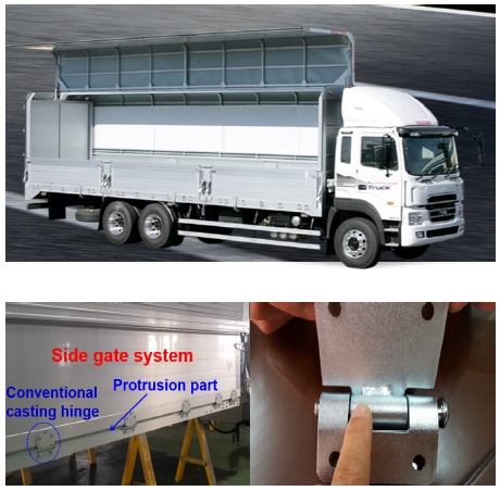
특장자동차의 박스형 차량은 적재된 화물의 보호 와 운송 중의 화물 추락 사고를 방지할 수 있고, 박스형 윙바디 차량은 양측방으로 sidegate가 개폐되는 구조로서 일반 화물차에 비하여 상하역이 용이하여 시장의 수요가 계속 증가하고 있다. 세월호 침몰 사고 이후 안전사고에 대한 사회적인 관심이 증폭되고 있으며, 도로는 기존에 건설되었고 그 후로 윙바디와 냉동탑 특장차는 전폭이 증가하면서 자동차관리법 2,500 mm 이하를 충족해야 하지만, 그림 1과 같이 sidegate의 힌지 돌출로 차폭이 2,500 mm를 초과한다. 이 경우, 내부 적재 공간의 폭이 작아져 화물의 적재 효율이 저하된다. 기본적으로 이러한 박스형 차량의 내부에 적재되는 화물용 팔레트(pallet)의 폭은 1,200 mm이다. 현재 윙바디 특수차는 sidegate와 주조 힌지의 두께 및 결합에 의하여 내부 적재함 폭이 2,400 mm 이하이므로, 팔레트 2개를 적재하지 못해 화물적재 효율이 저하되는 문제점이 지적되어 왔다. 또한 힌지의 홀에 삽입되는 부위 핀은 염화칼슘에 부식되고 용접부분에는 크랙(crack)이 발생하는 문제로 인하여 특장자동차의 안전사고를 위협하고 있다. 기존에 자동차 도어 힌지,1,2) 프레임3-6)의 구조 해석에 관한 일부 연구는 진행되었지만, 자동차관리법을 충족해야 하는 특장자동차의 적재함 힌지에 관한 구조해석은 전무하다.
이 연구는 기존 주조(casting)힌지로 구성된 sidegate 시스템에 비해 고효율·고강도 및 내부식성을 지닌 윙바디와 냉동탑 특장차용 단조힌지와 sidegate를 개발하는 것을 목표로 하되, 그 중 새롭게 개발한 단조힌지의 강도와 내부식성 특성을 파악하는 것이다.
2. 실험장치 및 방법
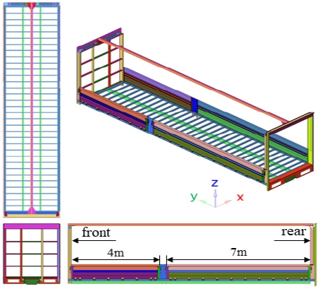
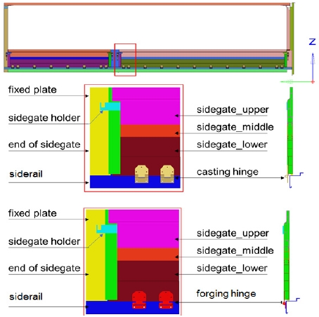
윙바디 sidegate는 힌지를 통해 gate를 개폐할 수 있는 구조이기 때문에 운행 중 도로 상황에 따라 내부 화물이 gate에 하중을 가한 경우가 발행할 수 있다. Sidegate는 Fig. 1과 같이 중앙부의 fixed plate를 기준으로 앞부분은 약 4 m, 뒷부분은 약 7 m의 gate로 분할된다. 이 연구는 sidegate가 발생 가능한 경우를 가정하고 fixed plate 및 이와 인접한 2개의 힌지에 대한 구조해석 모델을 만들어 하중에 대한 힌지의 응력집중 정도를 분석하였다. Siderail은 차량 하부의 cross member와 용접과 볼트로 체결되어 연결 부위를 모든 자유도에 대하여 구속하고 siderail에 연결된 fixed plate와 용접된 sidegate(top, middle, bottom)는 각각 억지 끼움으로 연결되는 구조임을 고려하여 해석 모델을 구성하였다. 또한 힌지 상부와 하부는 각각 sidegate와 siderail에 볼트 체결되는 구조이므로 이를 MPC(Multil Point Constraint)로 모사하였다. 이와 같은 방법으로 구성한 주요 구조해석 모델은 Fig. 3과 같이 구성되어 있고, 각 모델의 재질에 대한 물성치는 Table 1과 같다.
3. 결과 및 고찰
3.1 윙바디 sidegate 구조해석
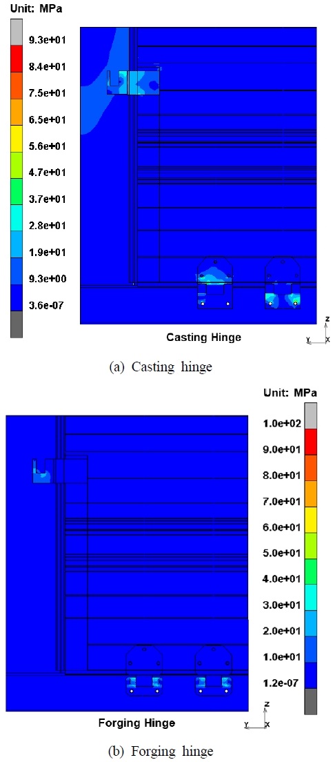
냉동탑과 윙바디 특장차용 상용 주조와 시제품 단조로 제작된 힌지의 구조해석 결과를 Fig. 4에 나타내었다. 최대응력은 힌지의 볼트 체결부에서 각각 93 MPa와 100 MPa 발생하여 약 7% 정도의 응력 레벨의 차이가 발생하였다. 주조 힌지의 경우 상부와 하부에 핀에 의해 조립되는 부분이 MPC로 모사되어 이곳에 넓은 영역의 응력 집중이 발생하였으며, Fig. 4(b) 단조힌지의 응력 또한 상부(upper)와 하부(lower)의 힌지 부품들이 체결되는 부분이 응력 집중되는 경향을 나타내고 있다.
CAE 해석 결과에서 하부 힌지의 size는 다르며, 이는 주조 힌지는 상용화된 제품이며, 단조 힌지는 개발한 시제품이다. 주조힌지의 하부는 단조힌지에 비해 사이즈가 크다. 구조해석은 형상과 항복 강도 등 재질에 따라 달라질 수 있으며, 제작법에는 큰 영향이 없는 걸로 판단된다.
구조해석 결과로는 응력 집중의 차이는 소폭 있으나 단조와 주조힌지로 국한되어 해석이 이루어져 경향성만 파악할 수 있으며, 이 연구가 지향하는 고강도를 지닌 sidegate에 연결되는 단조힌지의 실증 결과는 실험으로 파악할 수 있다.
3.2 단조힌지의 인장강도와 내부식성 평가
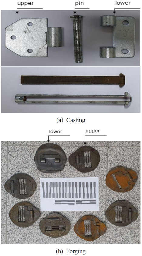
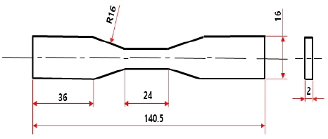
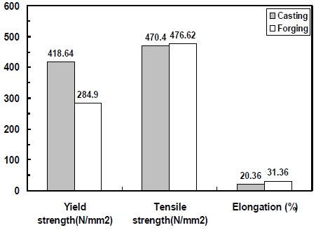
이 연구 대상의 sidegate 시스템은 Fig. 2와 같이 자동차 하부 프레임과 연결된 32개의 가로 방향 cross member와 고정되는데, 상판과 하판으로 구성된 sidegate는 힌지를 통해 개폐할 수 있다. 탄소강(SS400)을 이용하여 주조를 통해 제작된 힌지는 Fig. 5(a)와 같이 상판과 하판 및 연결 핀으로 구성되고, 단조를 통해 제작된 힌지는 Fig. 5(b)와 같이 상판과 하판으로 구성된다. 주조와 단조로 제작된 힌지의 기계적 물성을 확인하기 위하여 Fig. 6과 같이 ASTM E466 시편 형상으로 가공하여 인장 시험을 수행하였다. 주조와 단조 인장시험은 총 5회 수행하였고, 이에 대한 비교결과는 Fig. 7에 나타내었다. 개발한 단조힌지는 기존 주조힌지에 비해 항복강도는 저하되었지만, 인장강도는 약 1.3% 증가하였고 연신율은 약 54% 증가하였다. 이는 단조 가공은 200℃ 이상의 온도에서 가열 된 후 단조 금형을 통해 성형되는 과정에서 항복강도는 낮아지고 인장강도가 증가하기 때문이다. 기존 주조힌지가 아닌 단조힌지로 제작하여도 강도에 크게 문제가 되지 않고, 형상과 구조를 자유롭게 가공할 수 있어서 효율적이다.
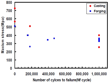
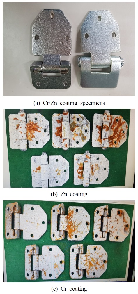
Fig. 8은 힌지 제조법에 따른 피로한도 시험결과를 나타내고 있다. 주조힌지는 5개 시험편을 통하여 얻은 피로한도는 최대응력 400 Mpa 106 사이클에서 파괴되지 않았다. 단조힌지는 8개 시험편을 이용하였으며, 최대응력은 325 Mpa로서, 개발 목표인 250 Mpa의 106 사이클에서 파괴되지 않았으며, 내구성 또한 확보되어서 실용화가 가능하다고 본다. Fig. 9는 기존 아연도금과 크롬도금한 샘플의 100 h 염무분수 시험 후 사진을 나타내고 있다. 아연도금한 주조힌지는 부식되는 표면적이 넓게 형성되어 있고, 표면 또한 거칠기가 두드러졌다. 이에 비해 크롬도금한 단조힌지는 아연도금한 단조힌지에 비해 부식되는 표면적이 작고, 표면 또한 훼손되지 않아 내부식성이 증가하였다. 크롬도금은 외관이 보기 좋고 대기 중에서 변색이 없으며, 염산 이외의 산에 대해서 부식되지 않는 성질을 가지고 있는 표면 처리기술이다.7-9)
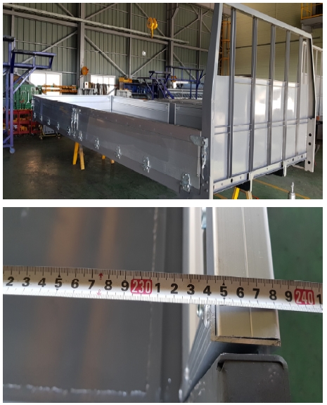
Fig. 10은 윙바디와 냉동탑 특장차용 실용화를 위한 sidegate 시스템과 단조힌지가 결합된 시작품의 전폭 규격 사진을 나타내고 있다. Sidegate와 단조힌지의 구조와 형상을 혁신적으로 개선하여 자동차관리법 전폭 규격인 2,500 mm 미만으로 자동차관리법을 충족하였고 이를 통하여 화물적재 효율이 개선되리라 판단한다.
4. 결 론
윙바디와 냉동탑 특장자동차용 sidegate 단조힌지의 강도와 내부식성 특성을 파악한 결과는 다음과 같다.
1) 개발한 단조힌지는 기존 주조힌지에 비해 인장강도는 약 1.3% 증가하였고 연신율은 약 54% 증가하하였다.
2) 단조힌지의 최대응력은 325 MPa로서, 개발 목표인 250 MPa의 106 사이클의 피로한도에서 파괴되지 않아 내구성을 확보하였다.
3) 크롬도금한 단조힌지는 100 h 염무분수 시험에서 아연도금된 주조힌지에 비해 도막에 균열이 일어나지 않았고, 부식면적이 적게 발생하여 내부식성이 향상되었다.
4) 윙바디 특장차용 시제품 sidegate 시스템의 전폭은 2,500 mm 미만으로 개발 목표치를 달성하였고 향후 실용화가 가능하다.
Author contributions
C. K. Seo; Conceptualization, experiment and writing-original draft. S. W. Choi; Structural analysis
References
- J. U. Cho, 2010, "Structural Analysis on Door Hinge of Car", Journal of the Korean Society for Manufacturing Process Engineering, Vol. 9, No. 2, pp. 33-39.
- H. J. Son, S. H. Rhee and D. J. Kim, 2018. "Plastic Hinge Modeling Based on Lumped Plasticity using a Generalized Finite Element Method", Journal of Computational Structural Engineering Institute of Korea, Vol. 31, No. 6, pp. 381-388.
- J. H. Lee, 2015, "A Durability Study due to the Model of Vehicle Monocoque Body Frame", Asia-pacific Journal of Multimedia Services Convergent with Art, Humanities, and Sociology, Vol. 5, No. 5, pp. 486-496.
-
S. S. Kim, K. S. Kim, D. S. Choi, S. H. Park, S. H. Kim and J. U. Cho, 2012, "Structural Strength Analysis at Cushion Frame and Back Frame of Automotive Seat", Journal of the Korea Academia-Industrial, Vol. 13, No. 11, pp. 4956-4962.
[https://doi.org/10.5762/KAIS.2012.13.11.4956]

- D. H. Han and S. Ha, 2019, "Development of Lightweight Composite Sub-frame in Automotive Chassis Parts Considering Structure & NVH Performance", Composites Research, Vol. 32, No. 1, pp. 21-28.
-
Y. S. Song, K. D. Hur and I. S. Son, 2016, "Development of Experimental Equation of Hood Frame for Vehicle Considering Operating Angle", Journal of the Korean Society for System Engineering", Vol. 20, No. 3, pp. 57-63.
[https://doi.org/10.9726/kspse.2016.20.3.057]

-
S. Y. Kang and D. W. Lee, 2014, "Study on Improvement of Mechanical Properties after Heat Treatment of Hard Chromium Electrodeposits with Additives", Journal of the Korean Institute of Surface Engineering, Vol. 47, No. 3, pp. 116-120.
[https://doi.org/10.5695/JKISE.2014.47.3.116]

-
J. Y. Lee, N. V. Phuong, S. H. Lim, S. Z. Han and S. C. Kwon, 2011, "The Effect of Polyethylene Glycol on the Trivalent Chromium Electroplating", Journal of the Korean Institute of Surface Engineering, Vol. 44, No. 1, pp. 7-12.
[https://doi.org/10.5695/JKISE.2011.44.1.007]

- I. S. Oh and T. H. Lee, 2006, "Effect of Plating Condition and Plating Rate on the Magnetic Properties of Electroless Ni-Cu-P Deposits", Vol. 10, No. 3, pp. 58-66.

