Dynamic Behavior of Cracked Timoshenko Beams Subjected to Sub-tangential Follower Force
Abstract
In this paper, the purpose is to investigate the stability and variation of the natural frequency of a cracked Timoshenko cantilever beam subjected to sub-tangential follower force and a tip mass. In addition, an analysis of the flutter instability of a cantilever beam according to the change of slenderness ratio is studied. The governing differential equations of a Timoshenko beam, subjected to an end tangential follower force, are derived via Hamilton’s principle. The two coupled governing differential equations are reduced to one-fourth order ordinary differential equation in terms of the flexural displacement. Finally, the influence of the slenderness ratio, a tip mass on the critical follower force, and the natural frequency of a Timoshenko beam are investigated. It is found that a difference of only 29% between the first natural frequency of the Euler beam model and that of the Timoshenko beam exists in the special case. By using the results of this paper, a judgment base is obtained as regards the choice of cracked beam models for the effect of the slenderness ratio and sub-tangential follower force. Furthermore, the effect of crack on the dynamic behavior of beams with a tip mass is investigated.
Keywords:
Cracked Timoshenko beam, Sub-tangential follower force, Slenderness ratio, Tip mass, Stability1. Introduction
The effect of cracks on the dynamic behavior of structure elements has been the subject of several investigations. When a structure is subjected to damage, its dynamic response is varied due to the change of its mechanical characteristics. Historically, Beck1) was the first to study the stability of a uniform cantilever column subjected to a compressive follower force at the free end. In 1976, Kounadis and Katsikadelis2) investigated the effects of the shear deformation and rotary inertia on the behavior of Beck’s column. Yoon and Kim3) studied the effect of the inertia moment of a tip mass on the stability of Beck’s column. Lee et al.4) investigated the influences of the slenderness ratio, the tangency coefficient, and the elastically restrained boundary conditions on the critical load and the elastic instability of a uniform Timoshenko beam subjected to an end sub-tangential follower force. Recently, Dentiko5) has investigated the lumped damping and stability of Beck’s column with a tip mass. Also, Rao and Rao6) studied the post-critical behavior of Euler and Beck’s columns which are resting on an elastic foundation. The effect of tip mass on the natural frequency of an elastically restrained column is investigated.7,8) Dado and Abuzeid9) studied a modeling and analysis algorithm for cracked beams by considering the coupling between the bending and axial modes of vibration. Chondros and Dimarogonas10,11) studied the effect of the crack epth and position on the dynamic behavior of a cantilevered beam. They showed that the increase of the crack depth reduces the natural frequency of the beam. Also, they used an energy method and a continuous cracked beam theory for analyzing the transverse vibration of cracked beams. Lin12) investigated the direct and inverse methods on the free vibration analysis of the simply supported beams with a crack. The method is based on modeling the beam according to the Timoshenko beam theory and presents the crack as a mass-less rotational spring. Choi and Byun13) stuied the sensitivity analysis algorithm for the natural frequency of a torsional shafting by expanding the transfer stiffness coefficient method.
The above studies were all mostly about the stability problem of the beam according to follower force, tip mass, slenderness ratio, and spring coefficient. In this paper, the effect of the slenderness ratio and tip mass on the natural frequency of a uniform-cracked Timoshenko and Euler beam subjected to an end sub-tangential follower force is studied. Generally, choosing which of two beam models (Euler-Bernoulli beam and Timoshenko beam model) to use is largely dependent on the beam geometry and the number of vibration modes. Therefore, the purpose of this paper is to present a base of judgment for choosing cracked beam models to achieve a slenderness ratio effect. Also, the effect of crack depth and position on the dynamic behavior of beams with a tip mass and sub-tangential follower force is investigated.
2. Equations of motion
2.1 Timoshenko beam with sub-tangential follower force
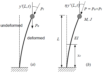
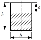
Fig. 1 shows the model of a cracked Timoshenko beam subjected to sub-tangential follower force and a tip mass. The magnitude of tip mass is depicted as M whose moment of inertia of mass is J. xc is the crack position from the clamped end of a beam. L is the total length of the beam and η is the sub-tangential parameter with the range 0 ≤ η ≤ 1. The value η = 0 corresponds to a pure dead load and thus to a Euler buckling problem. The value η = 1 corresponds to a pure follower load and thus to Beck’s flutter problem. It is noted that the beam subjected to force with the range 0 ≤ η ≤ 1 is a sub-tangential follower force. Pa and Pt are the axial compressive force of magnitude and a pure follower force of magnitude, respectively. Fig. 2 represents a cross-section of the cracked beam. In Fig. 2, a is the crack depth, while b and h are the rectangular cross-section dimensions. Two equations of motion are derived respectively for the two parts of the beam separated by the cracked sections.
As a basis for analysis, a uniform Timoshenko beam should be considered. The equations of motion for the free bending vibration of a Timoshenko beam can be written as follows:
| (1) |
| (2) |
where, y(x,t) is the transverse displacement and ψ(x,t) is the slope due to bending. The above equations(1 and 2) are coupled. E and G are the Young’s and shear modulus, respectively. I is the second moment of area of the cross-section, A is the cross-sectional area, and m is the mass per unit length of the beam. k is the shear coefficient depending on the shape of the cross-section and the variation frequency of the beam. The associated boundary conditions of Timoshenko beam are the following:
| (3) |
where, a prime (ʹ) denotes the x-derivatives and the number of sub-index is the segment number of beam due to a crack, respectively. By eliminating ψ(x,t) from Equations 1 and 2, fourth order differential equation may be written as follows:
| (4) |
where, ρ is the mass density of the beam material. It is assumed that the beam undergoes harmonic motion:
| (5a,b) |
where, and ωf are the angular frequency of vibration. Sub-index n is the number of the segments due to the crack. Substituting equations (5a,b) into equation (4), one obtains the governing differential equation of a uniform Timoshenko beam:
| (6) |
The dimensionless boundary conditions of a beam are:
| (7) |
The dimensionless boundary conditions for the transverse deflection, bending moment, shear force, and slope at the cracked section(ξ = ξc) of a beam meanwhile are:
| (8) |
For simplicity, the following dimensionless quantities are introduced:
| (9) |
In this study, the slenderness ratio is s = 1/r. The solutions of the differential equation are easily found to be:
| (10a) |
| (10b) |
where
and
Similarly, for the slope of the deflection curve of a Timoshenko beam, one can easily derive that:
| (11a) |
| (11b) |
where
.
2.2 Crack modeling
The bending vibrations of a uniform Timoshenko beam are considered in the plane, which is assumed to be a plane of symmetry for any cross-section. The additional strain energy due to the crack can be taken in the form of a flexibility coefficient expressed in terms of the stress intensity factor, which can be derived by Castigliano’s theorem in the linear elastic range. Therefore, the local flexibility is defined by:
| (12) |
where, v is the Poisson’s ratio and the dimensionless parameters and Ft(α) are:
| (13) |
In this equation, ζ = πα/2 , H is the dimensionless height of a beam. The relation of H and s is defined as .
In Equation (8), the parameter kR is C-1. The natural frequency of a cracked beam can be obtained through the following equation of matrix form:
| (14) |
where X = [a1 a2 a3 a4 a5 a6 a7 a8 ]T.
3. Numerical results and discussion
In this study, the effect of sub-tangential follower force and tip mass on the natural frequency of the cracked Timoshenko beams according to the variation of slenderness ratio is investigated. First of all, the accuracy of the present numerical results needs to be confirmed. Table 1 represents a comparison between the present results and the results of Ref. (13) for the natural frequency of Timoshenko cantilever beam without a crack according to the slenderness ratio. These results show that this study’s findings are in good agreement with the references for the equal value of parameters.
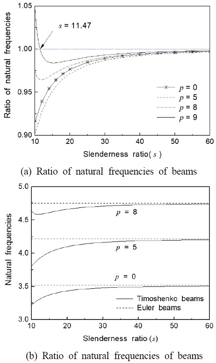
Fig. 3 shows the effect of follower force on the natural frequencies of Timoshenko cantilever beam without a crack for the first vibration mode. In this case, μ = j = 0 and η is 1. The horizontal axis gives the ratio of natural frequencies (natural frequency of Timoshenko beam / natural frequency of Euler beam) while the vertical axis is the slenderness ratio of a beam. In Fig. 3(a), the natural frequency ratio of the case of without follower force is larger than the case of with follower force in the special range p < 7.4. In the case of p = 9, the natural frequency of Euler beam is smaller than the case of Timoshenko beam. In Fig. 3, a difference of about 3% is found between the first natural frequency of the Euler beam model and that of the Timoshenko beam model in the case for s = 10. Generally, as the slenderness ratio is increased, the natural frequency of cantilever beams is increased. In the case of p = 8, the natural frequency of Timoshenko beam decreases monotonically upon increasing the slenderness ratio in the range of 10 ≤ s ≤13.
Fig. 4 shows the effect of follower force on the natural frequency of Timoshenko beam without a crack and the variation of the natural frequency of the beams. In these cases, μ = 1, j = 1 and η is 1. In Fig. 4, the critical follower force is p = 8.88 and p = 6.31 for the Euler beam and Timoshenko beam models, respectively. Therefore, one must choose the Timoshenko model in the case of s = 20 because the Euler beam reaches an unstable condition.
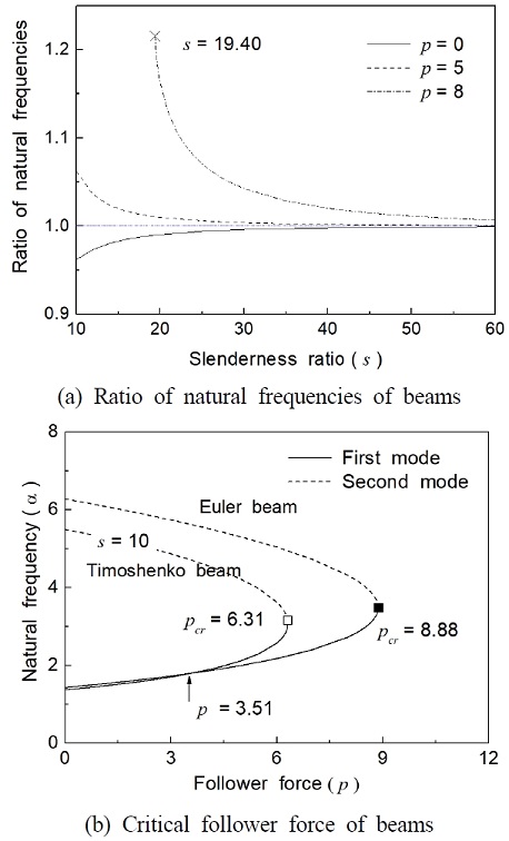
Effect of follower force on natural frequencies and critical value of Timoshenko beam without crack (μ = 1, j = 0.1, η = 1)
Fig. 5 shows the natural frequency of cracked beams according to the effect of a tip mass. Generally, as the tip mass and its inertial moment are increased, the natural frequency of cracked beams is decreased. The effect of the inertial moment of a tip mass on the natural frequency change of beams is shown in Fig. 5(a). When the inertial moment is constant, the natural frequencies of cracked beams increase monotonically with increasing slenderness ratio. The effect of the slenderness ratio is very low for the range of about s > 40.
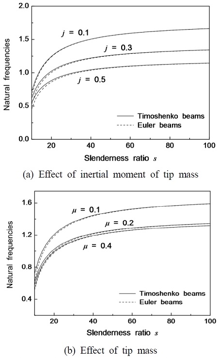
Natural frequency of cracked beams according to the effect of tip mass(α = 0.3,ξc = 0.4,p = 5 and η = 0.6)
Fig. 5(b) represents the effect of tip mass on the natural frequency of cracked beams. When the value of the tip mass is constant, the natural frequencies of cracked beams increase with increasing the slenderness ratio of cantilever beam.
Fig. 6 shows the effect of a crack on the natural frequency and slenderness ratio of cantilever beam. In Fig. 6(a) represents the effect of crack depth on the natural frequency of beams. When the crack depth is 0.5, the natural frequencies of Euler beam and Timoshenko beam have almost equal values. In the case of α = 0.1, the slenderness ratio is proportionate to the natural frequency of Euler beam, but it has the inverse tendency for the Timoshenko beam. The effect of crack position on the natural frequency of beam is shown in Fig. 6(b). Generally, as the crack position moves to the end of the cantilever beam, the natural frequency becomes low gradually. In this study, however, when the crack position is 0.4, it has minimum natural frequency of beam because of the effect of sub-tangential follower force.
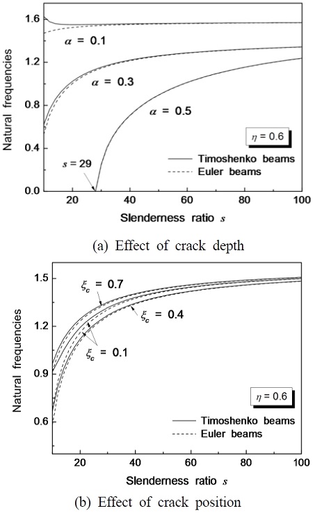
Natural frequencies of beams with sub-tangential follower force according to crack effect(j = 0.2,μ = 0.2,p = 5 and η = 0.6)
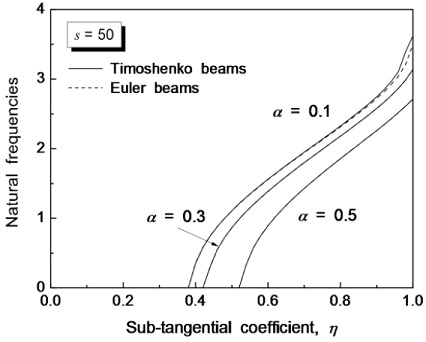
Fig. 7 shows the effects of the crack depth and the sub-tangential coefficient on the natural frequency of beams. In this case, the slenderness ratio is 50. As the crack depth is increased, the effect of sub-tangential coefficient becomes very low. In Fig. 7, when the natural frequency is 0, the beams approach an unstable condition. As the crack depth is increased, the unstable range of beams due to the sub-tangential coefficient becomes wide.
4. Conclusions
In this paper, the effect of the slenderness ratio and tip mass on the natural frequency of a uniform cracked Timoshenko beam subjected to the sub-tangential follower force is studied. The main results of this study are summarized as follows:
As the crack depth is increased, the unstable range of beams by the sub-tangential coefficient and the unstable range of beams by the sub-tangential coefficient are increased. When the tip mass and its inertial moment are constant, the natural frequencies of cracked beams increase monotonically with increasing slenderness ratio. The effect of slenderness ratio on the natural frequency of cracked beams is extremely low at the range of about s > 40.
By using the results of this paper, we can obtain the judgment standard as regards the choice of cracked beam models for the effect of slenderness ratio and sub-tangential follower force.
References
-
M. Beck, 1952, "Die Knicklast des Einseitig Eingespannten, Tangential Gedrückten Stables", ZAMP., Vol. 3, pp. 225-228.
[https://doi.org/10.1007/BF02008828]

-
A. Kounadis and J. T. Katsikadelis, 1976, "Shear and Rotatory Inertia Effect on Beck's Column", J. of Sound Vib., Vol. 49, No. 2, pp. 171-178.
[https://doi.org/10.1016/0022-460X(76)90494-6]

- H. I. Yoon and K. S. Kim, 1984, "The Influence of Inertial Moment of Tip Mass on the Stability of Beck’s Column", Trans. of KSME., Vol. 8, No. 2, pp. 119-126.
-
S. Y. Lee, T. Y. Chen and W. R. Wang, 1995, "Non-conservative Instability of a Timoshenko Beam Subjected to a Partially Tangential Follower Force", J. of Sound Vib., Vol. 188, No. 1, pp. 25-38.
[https://doi.org/10.1006/jsvi.1995.0576]

-
F. M. Detinko, 2003, "Lumped Damping and Stability of Beck Column with a Tip Mass", J. of Solids Struct., Vol. 40, pp. 4479-4486.
[https://doi.org/10.1016/S0020-7683(03)00298-1]

-
B. N. Rao and G. V. Rao, 2004, "Post-critical Behaviour of Euler and Beck Columns Resting on an Elastic Foundation", J. of Sound Vib., Vol. 276, pp. 1150-1158.
[https://doi.org/10.1016/j.jsv.2003.11.007]

-
K. Sato, 1996, "Instability of a Clamped- elastically Restrained Timoshenko Columns Carrying a Tip Load, Subjected to a Follower Force", J. of Sound and Vib., Vol. 194, No. 4, pp. 623-630.
[https://doi.org/10.1006/jsvi.1996.0381]

-
B. K. Lee, G. Li, S. J. Oh and G. S. Kim, 2005, "Stability Analysis of Beck's Column with a Tip Mass Restrained by a Spring", Trans. of KSNVE, Vol. 15, No. 11, pp. 1287-1294.
[https://doi.org/10.5050/KSNVN.2005.15.11.1287]

-
M. H. F. Dado and O. Abuzeid, 2003, "Coupled Transverse and Axial Vibratory Behaviour of Cracked Beam with End Mass and Rotary Inertia", J. of Sound Vib., Vol. 261, No. 4, pp. 675-696.
[https://doi.org/10.1016/S0022-460X(02)01004-0]

-
T. G. Chondros and A. D. Dimarogonas, 1989, "Dynamic Sensitivity of Structures to Cracks", J. of Vib. Acoustics, Stress and Reliability in Design, Vol. 111, No. 3, pp. 251-256.
[https://doi.org/10.1115/1.3269849]

-
T. G. Chondros and A. D. Dimarogonas, 1998, "Vibration of a Cracked Cantilever Beam", J. of Vib. Acoustics, Vol. 120, No. 3, pp. 742-746.
[https://doi.org/10.1115/1.2893892]

-
H. P. Lin, 2004, "Direct and Inverse Methods on Free Vibration Analysis of Simply Supported Beams with a Crack", Eng. Struct., Vol. 26, No. 4, pp. 427-436.
[https://doi.org/10.1016/j.engstruct.2003.10.014]

-
M. S. Choi and J. H. Byun, 2012, "Sensitivity Analysis for Natural Frequency of Torsional Shafting with Constant Cross Section Using Transfer of Stiffness Coefficient", J. of KSPSE., Vol. 16, No. 2, pp. 11-16.
[https://doi.org/10.9726/kspse.2012.16.2.011]

- A. K. Igor and I. L. Olga, 2001, "Formulas for Structural Dynamics", McGraw-Hill, New York.

